
Page 249 - Tandem Techniques
P. 249
Page 231
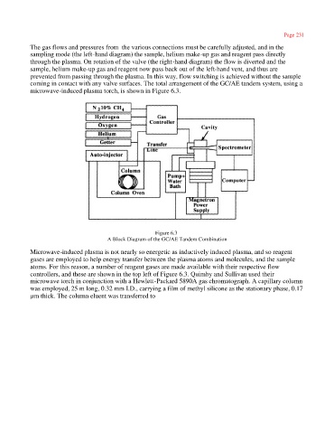
The gas flows and pressures from the various connections must be carefully adjusted, and in the
sampling mode (the left-hand diagram) the sample, helium make-up gas and reagent pass directly
through the plasma. On rotation of the valve (the right-hand diagram) the flow is diverted and the
sample, helium make-up gas and reagent now pass back out of the left-hand vent, and thus are
prevented from passing through the plasma. In this way, flow switching is achieved without the sample
coming in contact with any valve surfaces. The total arrangement of the GC/AE tandem system, using a
microwave-induced plasma torch, is shown in Figure 6.3.
Figure 6.3
A Block Diagram of the GC/AE Tandem Combination
Microwave-induced plasma is not nearly so energetic as inductively induced plasma, and so reagent
gases are employed to help energy transfer between the plasma atoms and molecules, and the sample
atoms. For this reason, a number of reagent gases are made available with their respective flow
controllers, and these are shown in the top left of Figure 6.3. Quimby and Sullivan used their
microwave torch in conjunction with a Hewlett-Packard 5890A gas chromatograph. A capillary column
was employed, 25 m long, 0.32 mm I.D., carrying a film of methyl silicone as the stationary phase, 0.17
µm thick. The column eluent was transferred to