
Page 266 - Tandem Techniques
P. 266
Page 248
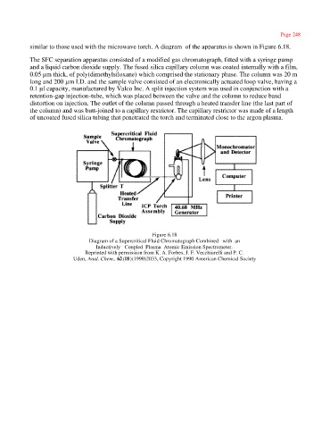
similar to those used with the microwave torch. A diagram of the apparatus is shown in Figure 6.18.
The SFC separation apparatus consisted of a modified gas chromatograph, fitted with a syringe pump
and a liquid carbon dioxide supply. The fused silica capillary column was coated internally with a film,
0.05 µm thick, of poly(dimethylsiloxane) which comprised the stationary phase. The column was 20 m
long and 200 µm I.D. and the sample valve consisted of an electronically actuated loop valve, having a
0.1 µl capacity, manufactured by Valco Inc. A split injection system was used in conjunction with a
retention-gap injection-tube, which was placed between the valve and the column to reduce band
distortion on injection. The outlet of the column passed through a heated transfer line (the last part of
the column) and was butt-joined to a capillary restrictor. The capillary restrictor was made of a length
of uncoated fused silica tubing that penetrated the torch and terminated close to the argon plasma.
Figure 6.18
Diagram of a Supercritical Fluid Chromatograph Combined with an
Inductively Coupled Plasma Atomic Emission Spectrometer.
Reprinted with permission from K. A. Forbes, J. F. Vecchiarelli and P. C.
Uden, Anal. Chem., 62(18)(1990)2033, Copyright 1990 American Chemical Society