
Page 123 - The Art and Science of Analog Circuit Design
P. 123
Analog Breadboarding
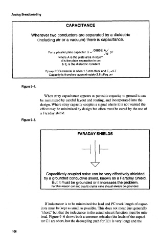
CAPACITANCE
Wherever two conductors are separated by a dielectric
(including air or a vacuum) there is capacitance.
QQQCC A /
For a parallel plate capacitor C = r /^ pF
where A is the plate area in sq.cm
d is the plate separation in cm
& E r is the dielectric constant
Epoxy PCB material is often 1.5 mm thick and E r =4.7
Capacity is therefore approximately 2,8 pf/sq,cm
Figure 9-4,
When stray capacitance appears as parasitic capacity to ground it can
be minimized by careful layout and routing, and incorporated into the
design. Where stray capacity couples a signal where it is not wanted the
effect may be minimized by design but often must be cured by the use of
a Faraday shield.
Figure 9-5.
Capacitively coupled noise can be very effectively shielded
by a grounded conductive shield, known as a Faraday Shield.
But it must be grounded or it increases the problem.
For this reason coil and quartz crystal cans should always be grounded.
If inductance is to be minimized the lead and PC track length of capac-
itors must be kept as small as possible. This does not mean just generally
"short," but that the inductance in the actual circuit function must be min-
imal. Figure 9-6 shows both a common mistake (the leads of the capaci-
tor Cl are short, but the decoupling path for IC1 is very long) and the
106