
Page 127 - The Art and Science of Analog Circuit Design
P. 127
Analog Breadboarding
plaae has minimal resistance and inductance, but its impedance may still
be too great at high currents or high frequencies. Sometimes a break in a
ground plane can configure currents so that they do not interfere with each
other; sometimes physical separation of different subsystems is sufficient.
Figure 9-12.
The breadboard ground consists of a single layer
of continuous metal, usually (unetched) copper-clad PCB material.
In theory all points on the plane are at the same potential,
but in practice it may be necessary to configure ground currents by
means of breaks in the plane, or careful placement of sub-systems.
Nevertheless ground plane is undoubtedly the most effective ground
technique for analog breadboards.
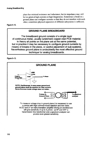
Figure 9-13,
GROUND PLANE
NOTE: Oscilloscope, in-amp power ground and
ground plane must be common for bias currents.
Some Common-mode voltage does not matter.
Probes to
Ground Plane
To measure voltage drop in ground plane it Is necessary to use
a device with high common-mode rejection and low noise.
At DC and LF an Instrumentation amplifier driving an oscilloscope
will give sensitivity of up to 5 uV/cm - at HF and VHF a
transmission line transformer and a spectrum analyser can
provide even greater sensitivity.
110