
Page 254 - The Combined Finite-Discrete Element Method
P. 254
STRAIN SOFTENING BASED SMEARED FRACTURE MODEL 237
0.1
0.14 Total energy - mesh A 0.09 Strain energy - mesh A
Total energy - mesh B Strain energy - mesh B
0.12 0.08
External work - mesh A External work - mesh A
0.07
0.1 External work - mesh B 0.06 External work - mesh B
Energy (kNm) 0.08 Energy (kNm) 0.05
0.06
0.04
0.04 0.03
0.02
0.02
0.01
0 0
0 5 10 15 20 0 50 100 150 200 250
Time (s) Time (s)
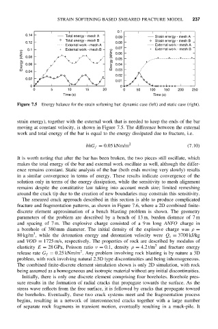
Figure 7.5 Energy balance for the strain softening bar: dynamic case (left) and static case (right).
strain energy), together with the external work that is needed to keep the ends of the bar
moving at constant velocity, is shown in Figure 7.5. The difference between the external
work and total energy of the bar is equal to the energy dissipated due to fracture, i.e.
bhG f = 0.05 kNm/m 2 (7.10)
It is worth noting that after the bar has been broken, the two pieces still oscillate, which
makes the total energy of the bar and external work oscillate as well, although the differ-
ence remains constant. Static analysis of the bar (both ends moving very slowly) results
in a similar convergence in terms of energy. These results indicate convergence of the
solution only in terms of the energy dissipation, while the sensitivity to mesh alignment
remains despite the constitutive law taking into account mesh size; limited remeshing
around the crack tip due to the creation of new boundaries may constrain this sensitivity.
The smeared crack approach described in this section is able to produce complicated
fracture and fragmentation patterns, as shown in Figure 7.6, where a 2D combined finite-
discrete element approximation of a bench blasting problem is shown. The geometry
parameters of the problem are described by a bench of 13 m, burden distance of 7 m
and spacing of 7 m. The explosive charge consisted of a 9 m long ANFO charge in
a borehole of 380 mm diameter. The initial density of the explosive charge was ρ =
3
80 kg/m , while the detonation energy and detonation velocity were Q e = 3700 kJ/kg
and VOD = 1725 m/s, respectively. The properties of rock are described by modulus of
3
elasticity E = 28 GPa, Poisson ratio ν = 0.1, density ρ = 4.2 t/m and fracture energy
2
release rate G f = 0.25 kNm/m . Any problem involving rock blasting is by nature a 3D
problem, with rock involving natural 2.5D type discontinuities and being inhomogeneous.
The combined finite-discrete element simulation shown is only 2D simulation, with rock
being assumed as a homogeneous and isotropic material without any initial discontinuities.
Initially, there is only one discrete element comprising four boreholes. Borehole pres-
sure results in the formation of radial cracks that propagate towards the surface. As the
stress wave reflects from the free surface, it is followed by cracks that propagate toward
the boreholes. Eventually, these two crack systems meet and the fragmentation process
begins, resulting in a network of interconnected cracks together with a large number
of separate rock fragments in transient motion, eventually resulting in a muck-pile. It