
Page 256 - The Combined Finite-Discrete Element Method
P. 256
DISCRETE CRACK MODEL 239
The problem of sensitivity to mesh orientation remains, and it is not easy to provide an
answer to the question of the extent to which the obtained fracture pattern is a function
of the initial mesh. This is because the final fracture pattern does not depend only on
the initial mesh, but also on all subsequent remeshings, which are in turn governed by
the creation of new boundaries. In other words, the mesh pattern is influenced by mesh
orientation, and in turn the transient meshes are a result of boundaries created by the frac-
ture pattern. The problem of sensitivity of the fracture pattern to mesh orientation in the
context of the smeared fracture and fragmentation model is also coupled with algorithmic
complexities involving permanent remeshing due to the creation of new boundaries and
the problems associated with it (transfer of variables, tracing of new contacts, perma-
nently changing size, topology and CPU and RAM requirements during execution of the
computer problem). Thus, in recent developments of the combined finite-discrete element
method, the emphasis is being placed on discrete crack based approaches.
7.3 DISCRETE CRACK MODEL
As explained above, the smeared crack model for fracture and fragmentation is cou-
pled with numerical difficulties and algorithmic complexities. Bearing in mind the other
complexities involved in combined finite-discrete element simulations, such as contact
detection and contact interaction, the transition from continua to discontinua algorithms
must be optimised both in terms of CPU time and RAM requirements. Recent research
efforts regarding fracture modelling in the context of the combined finite-discrete element
method have therefore also included the single crack model. The model presented in this
section is actually a combination of the smeared and single crack approaches. It was
designed with the aim of modelling multiple-crack situations, progressive fracture and
failure, including fragmentation and the creation of a large number of rock fragments of
general shape and size.
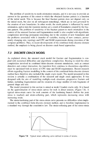
The model presented in this section is aimed at mode I loaded cracks only. It is based
on the approximation of stress-strain curves for rock in direct tension, (Figure 7.8). A
typical stress-strain curve for rock consists of the hardening branch (before the peak
stress is reached) and strain-softening part, which represents decreasing stress with
increasing strain.
The strain-hardening part of the stress-strain curve presents no difficulties when imple-
mented in the combined finite-discrete element method, and is therefore implemented in
a standard way through the constitutive law. The strain-softening part of the stress-strain
s
f t
e t e
Figure 7.8 Typical strain softening curve defined in terms of strains.