
Page 312 - The Combined Finite-Discrete Element Method
P. 312
POTENTIAL CONTACT FORCE IN 3D 295
2
3
0 1
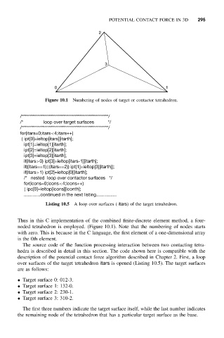
Figure 10.1 Numbering of nodes of target or contactor tetrahedron.
/******************************************************/
/* loop over target surfaces */
/******************************************************/
for(itars=0;itars<4;itars++)
{ ipt[0]=ieltop[itars][itarth];
ipt[1]=ieltop[1][itarth];
ipt[2]=ieltop[2][itarth];
ipt[3]=ieltop[3][itarth];
if(itars>0) ipt[3]=ieltop[itars-1][itarth];
if((itars==1)||(itars==2)) ipt[1]=ieltop[3][itarth]];
if(itars>1) ipt[2]=ieltop[0][itarth];
/* nested loop over contactor surfaces */
for(icons=0;icons<4;icons++)
{ ipc[0]=ieltop[icons][iconth];
.............continued in the next listing................
Listing 10.5 A loop over surfaces ( itars) of the target tetrahedron.
Thus in this C implementation of the combined finite-discrete element method, a four-
noded tetrahedron is employed. (Figure 10.1). Note that the numbering of nodes starts
with zero. This is because in the C language, the first element of a one-dimensional array
is the 0th element.
The source code of the function processing interaction between two contacting tetra-
hedra is described in detail in this section. The code shown here is compatible with the
description of the potential contact force algorithm described in Chapter 2. First, a loop
over surfaces of the target tetrahedron itars is opened (Listing 10.5). The target surfaces
are as follows:
• Target surface 0: 012-3.
• Target surface 1: 132-0.
• Target surface 2: 230-1.
• Target surface 3: 310-2.
The first three numbers indicate the target surface itself, while the last number indicates
the remaining node of the tetrahedron that has a particular target surface as the base.