
Page 313 - The Combined Finite-Discrete Element Method
P. 313
296 ALGORITHM IMPLEMENTATION
.........continued from previous listing.............
ipc[1]=ieltop[1][iconth];
ipc[2]=ieltop[2][iconth];
ipc[3]=ieltop[3][iconth];
if(icons>0) ipc[3]=ieltop[icons][iconth]];
if((icons==1)||(icons==2)) ipc[1]=ieltop[3][iconth];
if(icons>1) ipc[2]=ieltop[0][iconth];
/* set nodal coordinates */
...........continued in the next listing................
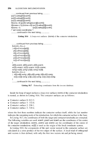
Listing 10.6 A loop over surfaces (icons) of the contactor tetrahedron.
.........continued from previous listing................
for(i=0;i<3;i++)
{ xt[i]=d1nccx[ipt[i]];
yt[i]=d1nccy[ipt[i]];
zt[i]=d1nccz[(ipt[i]];
xc[i]=d1nccx[(ipc[i]];
yc[i]=d1nccy[(ipc[i]];
zc[i]=d1nccz[(ipc[i]];
}
xt[3]=xcent; yt[3]=ycent; zt[3]=zcent;
xc[3]=xcenc; yc[3]=ycenc; zc[3]=zcenc;
xorig=xc[0]; yorig=yc[0]; zorig=zc[0];
for(i=0;i<4;i++)
{ xt[i]=xt[i]-xorig; yt[i]=yt[i]-yorig; zt[i]=zt[i]-zorig;
xc[i]=xc[i]-xorig; yc[i]=yc[i]-yorig; zc[i]=zc[i]-zorig;
}
.........continued in the next listing.................
Listing 10.7 Extracting coordinates from the in-core database.
Inside the loop of target surfaces a loop over surfaces icons of the contactor tetrahedron
is nested, as shown in Listing 10.6. The contactor surfaces are as follows:
• Contactor surface 0: 012-3.
• Contactor surface 1: 132-0.
• Contactor surface 2: 230-1.
• Contactor surface 3: 310-2.
where the first three numbers indicate the contactor surface itself, while the last number
indicates the remaining node of the tetrahedron, for which the contactor surface is the base.
In Listing 10.7, the coordinates of both the target and contactor tetrahedra are extracted.
The following variables are used: xcent, ycent and zcent are the coordinates of the centre
of the target tetrahedron; xcenc, ycenc and zcenc are the coordinates of the centre of
the contactor tetrahedron; xc[0] is used as the origin of the local coordinate system.
In Listing 10.8, the components of the unit vector normal to the contactor surface are
calculated as a cross product of the two edges of the surface. A local triad of orthogonal
unit vectors is then defined, with only the first two vectors xe and ye being stored.