
Page 314 - The Combined Finite-Discrete Element Method
P. 314
POTENTIAL CONTACT FORCE IN 3D 297
.......continued from previous listing.............
/* contactor normal, e-base and target points in e-base */
V3DCro(xnc,ync,znc,xc[1],yc[1],zc[1],xc[2],yc[2],zc[2]);
V3DNor(xe[0],xnc,ync,znc);
xe[0]=xc[1]; ye[0]=yc[1]; ze[0]=zc[1];
V3DNor(xe[1],xe[0],ye[0],ze[0]);
V3DCro(xe[1],ye[1],ze[1],xnc,ync,znc,xe[0],ye[0],ze[0]);
........continued in the next listing...............
Listing 10.8 Unit normal to the current contactor surface.
........continued from previous listing.............
/* contactor normal, e-base and target points in e-base */
for(i=0;i<4;i++)
{ V3DDot(dct[i],xnc,ync,znc,xt[i],yt[i],zt[i]);
V3DDot(ut[i],xt[i],yt[i],zt[i],xe[0],ye[0],ze[0]);
V3DDot(vt[i],xt[i],yt[i],zt[i],xe[1],ye[1],ze[1]);
}
if((dct[0]<=R0)&&(dct[1]<=R0)&&(dct[2]<=R0))continue;
.........continued in the next listing.............
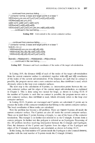
Listing 10.9 Distances and local coordinates of the nodes of the target sub-tetrahedron.
In Listing 10.9, the distance dct[i] of each of the nodes of the target sub-tetrahedron
from the current contactor surface is calculated, together with ut[i] and vt[i] coordinates
of the nodes of the current sub-tetrahedron. If the distances are such that no contact is
possible, the program moves onto a new contactor surface, thus continue is used, which
obviously refers to the loop over contactor surfaces.
The next step is the calculation of S-points, i.e. intersection points between the cur-
rent contactor surface and the edges of the current target sub-tetrahedron, as explained
in Chapter 2. This is done using two nested for loops, as shown in Listing 10.10. If
the number of S-points is such that no contact is possible, the program moves onto a
new contactor surface, thus continue is used, which obviously refers to the loop over
contactor surfaces.
In Listing 10.11, S-points are rearranged and C-points are calculated. C-points are in
essence the nodes of the contactor tetrahedron that belong to the current contactor surface.
The local coordinates of these nodes are calculated.
Now the problem has become a 2D problem. There are nspoin S-points all inside the
current contactor surface. The C-points are also all inside the current contactor surface.
There are in total three C-points forming a triangle, i.e. one of the bases of the contactor
tetrahedron. This triangle is in further text referred to as the C-triangle. S-points form a
convex polygon. In further text this polygon is referred as an S-polygon. Processing of
this 2D problem involves resolving intersection between the C-triangle and S-polygon.
First, the distances of the C-points and S-points from the edges of the S-polygon and
edges of the C-triangle, respectively, are calculated, as shown in Listing 10.12.
In this listing, the total number of C-points inside the S-polygon is also counted (inners),
together with the total number of S-points inside the C-triangle (innerc).