
Page 319 - The Combined Finite-Discrete Element Method
P. 319
302 ALGORITHM IMPLEMENTATION
.........continued from previous listing.............
V3DCro(xnt,ynt,znt,xt[1]-xt[0],yt[1]-yt[0],zt[1]-zt[0],
xt[2]-xt[0],yt[2]-yt[0],zt[2]-zt[0]);
V3DDot(theigh,xt[3]-xt[0],yt[3]-yt[0],zt[3]-zt[0],xnt,ynt,znt);
/* penetration at origin of the e-base and dp/du dp/dv; */
V3DDot(peneto,xc[0]-xt[0],yc[0]-yt[0],zc[0]-zt[0],xnt,ynt,znt);
V3DDot(penetu,xe[0],ye[0],ze[0],xnt,ynt,znt);
V3DDot(penetv,xe[1],ye[1],ze[1],xnt,ynt,znt);
peneto=peneto/theigh;
penetu=penetu/theigh;
penetv=penetv/theigh;
for(i=0;i<nbpoin;i++)
{ penetb[i]=peneto+ub[i]*penetu+vb[i]*penetv;
}
Listing 10.16 Calculation of penetration (contact overlap) at B-points.
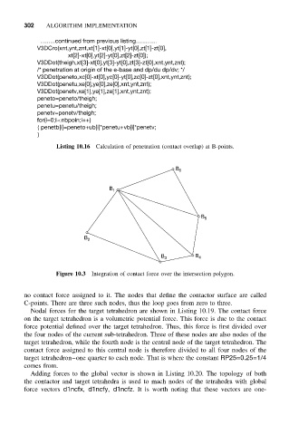
B 6
B 1
B 5
B 2
B 3 B 4
Figure 10.3 Integration of contact force over the intersection polygon.
no contact force assigned to it. The nodes that define the contactor surface are called
C-points. There are three such nodes, thus the loop goes from zero to three.
Nodal forces for the target tetrahedron are shown in Listing 10.19. The contact force
on the target tetrahedron is a volumetric potential force. This force is due to the contact
force potential defined over the target tetrahedron. Thus, this force is first divided over
the four nodes of the current sub-tetrahedron. Three of these nodes are also nodes of the
target tetrahedron, while the fourth node is the central node of the target tetrahedron. The
contact force assigned to this central node is therefore divided to all four nodes of the
target tetrahedron–one quarter to each node. That is where the constant RP25=0.25=1/4
comes from.
Adding forces to the global vector is shown in Listing 10.20. The topology of both
the contactor and target tetrahedra is used to mach nodes of the tetrahedra with global
force vectors d1ncfx, d1ncfy, d1ncfz. It is worth noting that these vectors are one-