
Page 12 - The Geological Interpretation of Well Logs
P. 12
- THE GEOLOGICAL INTERPRETATION OF WELL LOGS -
Table 1.1 Classification of the common wireline geophysical well measurements (in ‘open hole’).
Log Type Formation parameter measured
Mechanical measurements Caliper Hole diameter
Spontaneous measurements Temperature Borehole temperature
SP (self-patential} Spontaneous electrical currents
Gamma ray Natural radioactivity
Induced measurements Resistivity Resistance to electrical current
Induction Conductivity of electrical current
Sonic Velocity of sound propagation
Density Reaction to gamma ray bombardment
Photoelectric Reaction to gamma ray bombardment
Neutron Reaction to neutron bombardment
{measurement while drilling) or LWD (logging while
drilling) logs, by contrast, are made as a formation is
drilled. Quite different techniques are made to record magnatic
recording
MWD and LWD logs but the results are comparable to
the open hole wireline logs (see Section 1.6).
(0) (0) mechanical
Wireline logs are made using highly specialized equip- Geog winchiag
drum
ment entirely separate from that used for drilling.
Onshore, a motorized logging truck is used which brings logging
VAS cable
its array of surface recorders, computers and a logging
drum and cable to the drill site. Offshore, the sarne equip- a
ment is installed in a small cabin left permanently on the =<
Z
rig. Both truck and cabin use a variety of interchangeable
logging tools, which are lowered into the wel] on the Y
logging cable (Figure 1.2). U; vat an
Most modern logs are recorded digitally. The sam-
pling rate will normally be once every 15 cm (6 in),
although for some specialized logs it will be as low as 2.5
surtace
mm {0.1 in). An average well of say 2000 m will there- computer
fore be sampled over 12,000 times for each individual
tog, and for a suite of 8 or so typical logs, it will be
sampled over 100,000 times (although for some new,
specialised tools, this can be the sampling rate per WZ 1 down hole
metre!). At typical logging speeds, data transmission logging
tool
rates will vary from 0.05 kilobits per second for simpler
logs to over 200 kilobits per second for the new complex SN
logs. The huge amount of data representing each logging
run is fed into the computer of the surface unit. There is
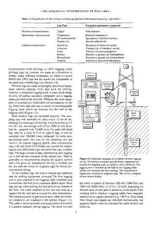
Figure 1.2 Schematic diagram of a modern wireline logging
generally an instantaneous display for quality control
set-up, The surface computer and etectronic equipment are
and a full print-out immediately the log is finished, but
housed in a logging truck {on land) or cabin (offshore). The
the raw data are stored on magnetic tape for future pro-
logging tool is winched up the hole by the logging cable
cessing and editing.
which also transmits the tool readings. The transmittal is
To run wireline logs, the hole is cleaned and stabilized digital and recorded on magnetic tape. The surface computer
and the drilling equipment extracted The first logging allows instant display.
tool is then attached to the logging cable (wireline) and
lowered into the hole to its maximum drilled depth. Most the cable at speeds of between 300 mvh (1000 ft/h) and
logs are run while pulling the tool up from the bottom of 1800 m/h (6000 ft/h), ie. 0.3 to 1.8 km/h, depending on
the hole. The cable attached to the tool acts both as a the tool used. As the cable is pulled in, so the depth of the
support for the too] and as a canal for data transmission. working tool is checked. Logging cables have magnetic
The outside consists of galvanized steel, while the electri- markers set at regular intervals (e.g. 100 ft or 25m) along
cal conductors are insulated in the interior (Figure 1.3). their length and depths are checked mechanically, but
The cable is wound around a motorized drum on to which apparent depths must be corrected for cable tension and
it is guided manually during logging. The drum will pult elasticity.