
Page 44 - The Geological Interpretation of Well Logs
P. 44
- THE GEOLOGICAL INTERPRETATION OF WELL LOGS -
mixing of the two solutions takes place by ionic diffu- in the more dilute solution. A potential is created between
sion. The Cl ion is both smaller and more mobile than the negatively charged dilute solution with excess Cl” and
the larger, slower Na* ion. The ions mix (diffuse), there- the positively charged, concentrated solution with excess
fore, at unequal rates, creating a charge separation. The Nat igure 5.3.2).
CI’ ion mixes the quickest, thus increasing its saturation The shale potential arises when the same two solutions
are in contact across a semi-permeable membrane. In the
S.P. circuit S.Plog
borehole, this, as the name suggests, is shale (Figure
Galvanometer
§.3,2}. Clay minerals which form shales, consist of layers
millivolts with Jarge negative surface charge. Because of charge
- e+
similarity, the negative chlonde ions effectively cannot
pass through the negatively charged shale layers, while
the positive sodium ions pass easily. The shale acts as a
impermeable = 200 tially across a shale membrane, an overbalance of Na*
selective barrier. As Na* ions therefore diffuse preferen-
I 100
ions is created in the dilute solution, and hence a positive
charge. A corresponding negative charge is produced
in the concentrated solution (Figure 5.3,2). The shale
permeable potential is the larger of the two electrochemical effects.
Cc
The actual spontaneous potential currents which are
measured in the borehole are, for the most part, a result
of the combination of the two electrochemical effects
Depth
described above. Consider a porous and permeable sand-
f- 400
stone penetrated by a borehole; the mud filtrate (for the
example) is less saline than the formation waters (Figure
5.4). Opposite the sandstone bed (permeable membrane)
My moving electroda
the less saline solution, the mud filtrate, will become
M2 earthed electrode
negatively charged as a result of the diffusion potential
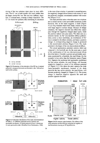
Figure 5.2 Dlustration of the principle of the SP Jog. A natural (cf. Figure 5.3,/). But above the sand, opposite the shale
potential is measured between an electrode in the well and an (semi-permeable membrane), because of the shale
earth at the surface.
potential the less saline solution, the mud filtrate, will
become positively charged (cf. Figure 5.3.2). The excess
charge is therefore negative opposite the sand and
positive opposite the shale.
1. DIFFUSION Membrane
POTENTIAL of porous s FORMATION | HOLE IS.P LOG
permeable relative millivolis
(17% of SP)
sand
charge — 2% +
3 suf
MEMBRARE < Lu
wo 5 ee
CONC Na Ct "DILUTE SOLUTION
a & 7 $a
7Be
£ # p+ OD
2
wo
5 ‘
i+ 4H
== (Ss
|"
of semi-
2. SHALE Membrane
POTENTIAL » 2: =
(83% of SP] permeable 5 2 -224
shale e. - —
& oe: -9
By =g5
§ -t#
MEMBRANE & -IKE
CONC No all 4~ A Ionut SOLUTION
-ae
a
fluids FORMATION WATER FILTRATE §=6MUD
| FORMATION | [ BOREHOLE |
higher salinity lower salinity
Figure 5.3 Schematic illustration of the main electrochemical
SP effects, (1) Diffusion potential across a porous and Figure 5.4 SP currents in the borehole. The effects of the
permeable membrane; (2) shale potential across a membrane shale potential and the diffusion potential act together at
of semi-permeable shale. (Modified from Desbrandes, 1968). bed boundaries causing an SP log deflection.