
Page 41 - The Geological Interpretation of Well Logs
P. 41
- CALIPER LOGS ~
Three main types of elliptical borehole have been stress regime of the country rock (Bell and Gough,
recognized, ‘keyseats’, “washouts’ and ‘breakouts’ 1979). Smail brittle fractures (spalling) occur in the bore-
(Figure 4.9). Washouts develop from general drilling hole around a rotating bit which, if there is unequal
wear, especially in shaly zones and dipping beds. On the horizontal stress in the formation, form in a preferential
geometry logs, a washout has a considerable vertical direction, that of the minimum horizontal stress, Sh
extent and both calipers are larger than the drill bit size {Figure 4.12, a). In more precise terms, compressive
with one caliper being much larger than the other. Shape shear fracturing of the borehole wal] is jocalised in
changes are variable and gradual (Figures 4.9¢; 4.10,2). the direction of the minimum horizontal formation
Keyseats are asymmetric oval holes, formed by wear stress Sh., and is the cause of breakouts (Bell, 1990).
against the drill string at points where the borehole Laboratory experiments and empirical observations seem
inclination changes (doglegs) (Figure 4.95). Both to back up the theory (see Prensky, 1992b for a review
washouts and keyseats are general drilling phenomena: and references). Hence, breakouts indicate the present
breakouts, however, have a specific cause. day stress-field orientation and are independent of lith-
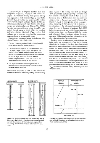
Breakouts are recognised using the following strict ology, dip and existing fractures or joints.
criteria (Figure 4.11) {i.e. Belt, 1990): Breakout studies to define in-situ stress fields are now
being carried out on many scales from the local to the
1. The tool must stop rotating (ideally the tool should
global. On the global scale, breakout derived stress-field
rotate before and after a breakout zone).
orientations are similar to those derived from earthquake
2. The calipers must separate to indicate an oval hole. studies and tend to indicate intra-plate tectonic stresses
The larger caliper should exceed hole gauge: the (Zoback et ai., 1989). On a local scale, breakout studies
smaller caliper should not be less than hole gauge have an importance for field development (Figure 4.13).
and its trace should be straight (the caliper difference Natural and artificial fractures are most likely to be
should be larger than 6 mm and the zone of oriented in the maximum horizontal stress direction Sh, .,
elongation greater than 1.5 m). The limits of the (Le. normal to breakouts) (Figure 4.12,6). Fracture
breakout should normally be well marked. connection between wells during field production ts then
more likely in this orientation (Bell, 1990). It is also
3. The larger diameter of hole elongation and its
possible that horizontal] drilling will be more stable in the
direction should not consistently coincide with the
Sh, (maximum horizontal stress) direction (Hillis and
azimuth of hole deviation.
Williams, 1992).
Breakouts are considered to form as a the result of the
interaction of stresses induced by drilling and the existing
Azimuth of Caliper axtensions
1.BREAKOUTS 2.WASHOUTS
calipers 1-3 {mm}
Hole diameter Hole diameter Mole diameter Hole diameter (degrees) increase
275 mm 15)
7M
275 mm_ 150) 275 mm 160 75 460)
4 i 4 4 1
le
5 f
2-4 —|:
ee eee
1-3
ie y
4.0
T
3
) 4 ole
‘ \
She
‘ A)
sy x
| y :
) 4 : Breakout
1 ‘
5
1 } ‘
|e, SH
b |S
x
gz
ep
Sot
Pp
"
dual-caliper log
Figure 4.10 Field examples of hole size enlargement seen on Figure 4.11 Schematic representation of the characteristics
the two-arm, dual caliper. 1. Breakouts, seen as well-defined, used to identify breakouts on caliper logs (re-drawn from
oval hole developments. 2, Washouts, seen as generalised Yassir and Dusseault, 1992).
hole ovality. Hole diameter increases to the left (from Cox,
1983).
31