
Page 37 - The Geological Interpretation of Well Logs
P. 37
- CALIPER LOGS -
caliper tool: varlabie resisianca only one of which is shown (Figure 4.4). The two hole
diameters measured by the two calipers are combined
-— with the directional elements of toa] orientation (pad 1
azimuth), hole deviation and azimuth of the deviation.
An integrated hole volume may be added as honzontal
wall
borehole
ticks on the depth column giving a continuous record of
hole volume (not on the example).
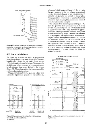
The calipers of the example presented (Figure 4.4),
show the geometry tool turning slowly as it moves
upwards in 4 persistently oval hole with a small diameter
of approximately 9" and a large diameter of approx-
imately L1", The larger diameter is oriented nearly north
to’ south as indicated by the pad | azimuth over the depth
Q-15 m (calipers 1-3 in larger diameter). At depth 30 m,
calipers 2-4 show the larger radius (approx. 11"), calipers
1-3 the smaller (approx. 9”). The rotation of the tool is
indicated by the persistent change in the pad | azimuth
and explains the caliper cross-over at depth 17 m (where
Figure 4,2 Schematic caliper tool showing the conversion of a both calipers show the same diameter but the hole is
mechanical movement to an electrical signal using a variable still oval). Above this, calipers 1-3 follow the larger
resistance. (Adapted from Serra, 1979).
diameter (approx. 11"), while calipers 2-4 follow the
smaller (approx. 9").
4.2, Log presentations
BOREHOLE GEOMETRY LOG
The caliper log is printed out simply as a continuous
DEVI (DEG)
value of hole diameter with depth (Figure 4.3). The curve
10.00
is traditionally a dashed line and usually plotted in track
| _. _H. AZI (DEG)
1. The horizontal scale may be inches of diameter or, in 40 360
| ___ PIAZ(OEG) _____|__ Tense) _
the differential caliper, expressed as increase or decrease -40
in hole diameter about a zero defined by the bit size
24.900 7
(Figure 4.3). The ordinary caliper log is accompanied by
0 24.0
a reference line indicating bit size.
The geometrical data from four-arm, dual-caliper tools hole
deviation
such as the dipmeter are presented in various formats,
5
hole
azimuth
41, CALIPER 2. DIFFERENTIAL CALIPER 10
calipers
BS (In) OIFFERENTIAL : 1-
(iinches}
CALIPER caliper tae \
CAL Cin} (reference) 1
e 16 1
£ . ’ calipers
a | } ea? 2-4
z I: SS) ] i inches)
|} re |
.
4+—!
20
| | 4 a} |
‘
\!
; © I
:
'
< 3s
r:
*
t ‘
‘J
s
bi size , 2 if Ee 4) ‘
bhi size hole size hole size . H i
30
diamater =171" dlamele: 19" diameter dlametor = *f
? (al arrowhead) O=relarence {at arrowhaead.
Figure 4.3 Presentation of the caliper log: (1), in ordinary Figure 4.4 Borehole geometry log presentation (see text for
format; (2), in differential format. explanation).
BS = bit size
27