
Page 160 - The Jet Engine
P. 160
Ice protection
unregulated supply of hot air via internal ducting from propeller blades and spinner and, when applicable,
the compressor. the oil cooler air intake cowling.
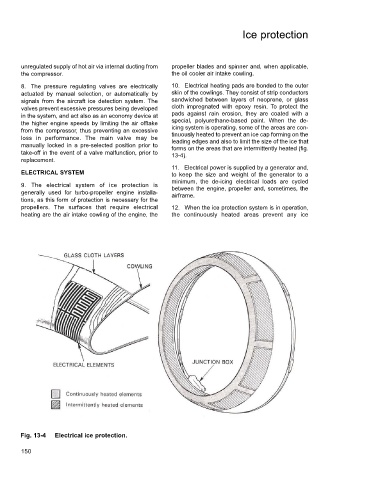
8. The pressure regulating valves are electrically 10. Electrical heating pads are bonded to the outer
actuated by manual selection, or automatically by skin of the cowlings. They consist of strip conductors
signals from the aircraft ice detection system. The sandwiched between layers of neoprene, or glass
valves prevent excessive pressures being developed cloth impregnated with epoxy resin. To protect the
in the system, and act also as an economy device at pads against rain erosion, they are coated with a
the higher engine speeds by limiting the air offtake special, polyurethane-based paint. When the de-
from the compressor, thus preventing an excessive icing system is operating, some of the areas are con-
tinuously heated to prevent an ice cap forming on the
loss in performance. The main valve may be leading edges and also to limit the size of the ice that
manually locked in a pre-selected position prior to forms on the areas that are intermittently heated (fig.
take-off in the event of a valve malfunction, prior to 13-4).
replacement.
11. Electrical power is supplied by a generator and,
ELECTRICAL SYSTEM to keep the size and weight of the generator to a
minimum, the de-icing electrical loads are cycled
9. The electrical system of ice protection is between the engine, propeller and, sometimes, the
generally used for turbo-propeller engine installa- airframe.
tions, as this form of protection is necessary for the
propellers. The surfaces that require electrical 12. When the ice protection system is in operation,
heating are the air intake cowling of the engine, the the continuously heated areas prevent any ice
Fig. 13-4 Electrical ice protection.
150