
Page 279 - The Jet Engine
P. 279
Overhaul
Balancing
40. Because of the high rotational speeds, any
unbalance in the main rotating assembly of a gas
turbine engine is capable of producing vibration and
stresses which increase as the square of the
rotational speed. Therefore very accurate balancing
of the rotating assembly is necessary.
41. The two main methods of measuring and
correcting unbalance are single plane (static)
balancing and two plane (dynamic) balancing. With
single plane, the unbalance is only in one plane i.e.,
centrally through the component at 90 degrees to the
axis. This is appropriate for components such as
individual compressor or turbine discs.
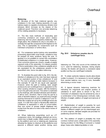
42. For compressor and/or turbine rotor assemblies Fig. 25-5 Unbalance couples due to
possessing appreciable axial length, unbalance may
be present at many positions along the axis. In centrifugal force.
general it is not possible to correct this combination
of distributed unbalance in a single plane. However,
if two correction planes are chosen, usually at axially
opposed ends of the assembly, it is always possible balancing run. This only occurs at the relatively low
to find a combination of two unbalance weights which r.p.m. used for balancing, because, during engine
are equivalent for the unbalances present in the running, the blades will assume a consistent radial
assembled rotor, hence two plane balancing.
position as they are centrifuged outwards.
43. To illustrate this point refer to fig. 25-5, the dis- 45. To obtain authentic balance results when blade
tribution of unbalance in the rotor has been reduced
to an equivalent system of two unbalances 'A' and scatter is present, it is necessary to record readings
'B'. The rotor is already in static balance because in from several balance runs, e.g. 8 runs, thereafter
this example 'A' and 'B' are equal and opposed. determining a vector mean.
However, when the part is rotating, each weight
produces its own centrifugal force in opposition to the 46. A typical dynamic balancing machine for
other causing unbalance couples, with the tendency indicating the magnitude and angular position of
to turn the part end-over-end. This action is restricted
by the bearings, with resultant stresses and vibration. unbalance in each plane is shown in fig. 25-6.
It will be seen, therefore, that to bring the part to a Correction of unbalance may be achieved by one or
state of dynamic balance, an equal amount of weight a combination of the following basic methods; redis-
must be removed at 'A' and 'B' or added at 'P' and 'O'. tribution of weight, addition of weight and removal of
When the couples set up by the centrifugal forces are weight.
equal, it is said that a part is dynamically balanced.
Unbalance is expressed in units of ounce-inches, 47. Redistribution of weight is possible for such
thus one ounce of excess weight displaced two assemblies as turbine and compressor discs, when
inches from the axis of a rotor is two ounce inches of blades of different weight can be interchanged and,
unbalance.
on some engines, clamped weights are provided for
positioning around the disc.
44. When balancing assemblies such as L.P.
compressor rotors, the readings obtained are incon-
sistent due to blade scatter. Blade scatter is caused 48. The addition of weight is probably the most
by the platform and root or retaining pin clearances common method used, certain parts of the assembly
allowing the blades to interlock at the platforms and having provision for the fitting of screwed or riveted
assume a different radial position during each plugs, heavy wire, balancing plates or nuts.
269