Page 61 - The Jet Engine
P. 61

11. The losses which prevent the turbine from being
                                                                       100 per cent efficient are due to a number of
                                                                       reasons.  A typical uncooled three-stage turbine
                                                                       would suffer a 3.5 per cent loss because of
                                                                       aerodynamic losses in the turbine blades. A further
                                                                       4.5 per cent loss would be incurred by aerodynamic
                                                                       losses in the nozzle guide vanes, gas leakage over
                                                                       the turbine blade tips and exhaust system losses;
                                                                       these losses are of approximately equal proportions.
                                                                       The total losses result in an overall efficiency of
                                                                       approximately 92 per cent.
                                                                       CONSTRUCTION

                                                                       12. The basic components of the turbine are the
                                                                       combustion discharge nozzles, the nozzle guide
                                                                       vanes, the turbine discs and the turbine blades. The
                                                                       rotating assembly is carried on bearings mounted in
                                                                       the turbine casing and the turbine shaft may be
                                                                       common to the compressor shaft or connected to it
                                                                       by a self-aligning coupling.
                                                                       Nozzle guide vanes
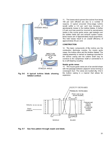
                                                                       13. The nozzle guide vanes are of an aerofoil shape
                                                                       with the passage between adjacent vanes forming a
                                                                       convergent duct. The vanes are located (fig. 5-8) in
                     Fig. 5-6   A typical turbine blade showing        the turbine casing in a manner that allows for
                                twisted contour.                       expansion.


                     Fig. 5-7   Gas flow pattern through nozzle and blade.

                                                                                                                  51
   56   57   58   59   60   61   62   63   64   65   66