
Page 63 - The Jet Engine
P. 63
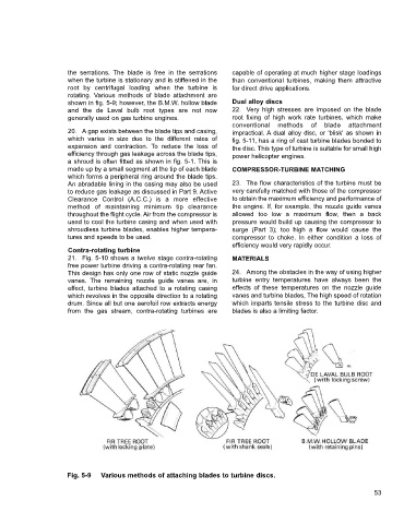
the serrations.  The blade is free in the serrations  capable of operating at much higher stage loadings
                      when the turbine is stationary and is stiffened in the  than conventional turbines, making them attractive
                      root by centrifugal loading when the turbine is  for direct drive applications.
                      rotating. Various methods of blade attachment are
                      shown in fig. 5-9; however, the B.M.W. hollow blade  Dual alloy discs
                      and the de Laval bulb root types are not now     22. Very high stresses are imposed on the blade
                      generally used on gas turbine engines.           root fixing of high work rate turbines, which make
                                                                       conventional methods of blade attachment
                      20. A gap exists between the blade tips and casing,  impractical. A dual alloy disc, or 'blisk' as shown in
                      which varies in size due to the different rates of  fig. 5-11, has a ring of cast turbine blades bonded to
                      expansion and contraction.  To reduce the loss of  the disc. This type of turbine is suitable for small high
                      efficiency through gas leakage across the blade tips,  power helicopter engines.
                      a shroud is often fitted as shown in fig. 5-1. This is
                      made up by a small segment at the tip of each blade  COMPRESSOR-TURBINE MATCHING
                      which forms a peripheral ring around the blade tips.
                      An abradable lining in the casing may also be used  23. The flow characteristics of the turbine must be
                      to reduce gas leakage as discussed in Part 9. Active  very carefully matched with those of the compressor
                      Clearance Control (A.C.C.) is a more effective   to obtain the maximum efficiency and performance of
                      method of maintaining minimum tip clearance      the engine. If, for example, the nozzle guide vanes
                      throughout the flight cycle. Air from the compressor is  allowed too low a maximum flow, then a back
                      used to cool the turbine casing and when used with  pressure would build up causing the compressor to
                      shroudless turbine blades, enables higher tempera-  surge (Part 3); too high a flow would cause the
                      tures and speeds to be used.                     compressor to choke. In either condition a loss of
                                                                       efficiency would very rapidly occur.
                      Contra-rotating turbine
                      21. Fig. 5-10 shows a twelve stage contra-rotating  MATERIALS
                      free power turbine driving a contra-rotating rear fan.
                      This design has only one row of static nozzle guide  24. Among the obstacles in the way of using higher
                      vanes.  The remaining nozzle guide vanes are, in  turbine entry temperatures have always been the
                      effect, turbine blades attached to a rotating casing  effects of these temperatures on the nozzle guide
                      which revolves in the opposite direction to a rotating  vanes and turbine blades, The high speed of rotation
                      drum. Since all but one aerofoil row extracts energy  which imparts tensile stress to the turbine disc and
                      from the gas stream, contra-rotating turbines are  blades is also a limiting factor.


                     Fig. 5-9   Various methods of attaching blades to turbine discs.

                                                                                                                  53