
Page 211 - The Master Handbook Of Acoustics
P. 211
186 CHAPTER NINE
bothersome reflections from walls and other surfaces to arrive at the
measuring position. If the pulse is short enough, the time gate can be
opened only for the desired sound pulse, shutting out the interfering
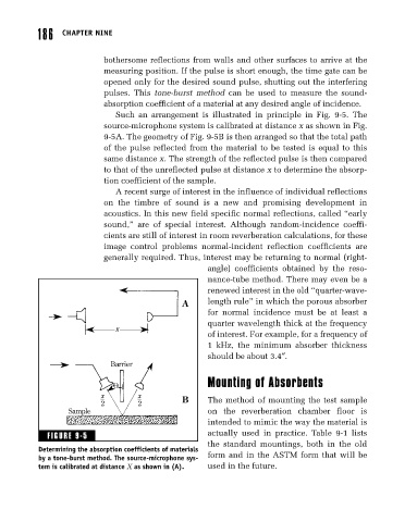
pulses. This tone-burst method can be used to measure the sound-
absorption coefficient of a material at any desired angle of incidence.
Such an arrangement is illustrated in principle in Fig. 9-5. The
source-microphone system is calibrated at distance x as shown in Fig.
9-5A. The geometry of Fig. 9-5B is then arranged so that the total path
of the pulse reflected from the material to be tested is equal to this
same distance x. The strength of the reflected pulse is then compared
to that of the unreflected pulse at distance x to determine the absorp-
tion coefficient of the sample.
A recent surge of interest in the influence of individual reflections
on the timbre of sound is a new and promising development in
acoustics. In this new field specific normal reflections, called “early
sound,” are of special interest. Although random-incidence coeffi-
cients are still of interest in room reverberation calculations, for these
image control problems normal-incident reflection coefficients are
generally required. Thus, interest may be returning to normal (right-
angle) coefficients obtained by the reso-
nance-tube method. There may even be a
renewed interest in the old “quarter-wave-
A length rule” in which the porous absorber
for normal incidence must be at least a
quarter wavelength thick at the frequency
x
of interest. For example, for a frequency of
1 kHz, the minimum absorber thickness
should be about 3.4″.
Barrier
Mounting of Absorbents
x x
2 2 B The method of mounting the test sample
Sample on the reverberation chamber floor is
intended to mimic the way the material is
FIGURE 9-5 actually used in practice. Table 9-1 lists
the standard mountings, both in the old
Determining the absorption coefficients of materials
by a tone-burst method. The source-microphone sys- form and in the ASTM form that will be
tem is calibrated at distance X as shown in (A). used in the future.