
Page 32 -
P. 32
.................................... Centrifugal Pumps
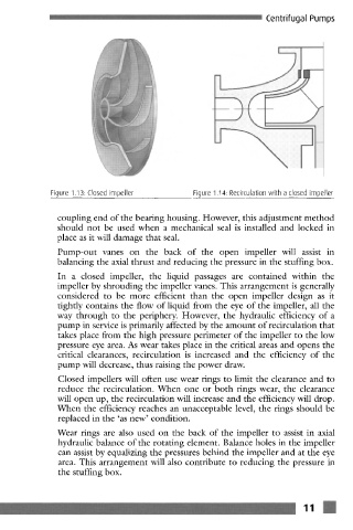
Figure 1.13: Closed impeller Figure 1.14: Recirculation with a closed impeller
coupling end of the bearing housing. However, this adjustment method
should not be used when a mechanical seal is installed and locked in
place as it will damage that seal.
Pump-out vanes on the back of the open impeller will assist in
balancing the axial thrust and reducing the pressure in the stuffing box.
In a closed impeller, the liquid passages are contained within the
impeller by shrouding the impeller vanes. This arrangement is generally
considered to be more efficient than the open impeller design as it
tightly contains the flow of liquid from the eye of the impeller, all the
way through to the periphery. However, the hydraulic efficiency of a
pump in service is primarily affected by the amount of recirculation that
takes place from the high pressure perimeter of the impeller to the low
pressure eye area. As wear takes place in the critical areas and opens the
critical clearances, recirculation is increased and the efficiency of the
pump will decrease, thus raising the power draw.
Closed impellers will often use wear rings to limit the clearance and to
reduce the recirculation. When one or both tings wear, the clearance
will open up, the recirculation will increase and the efficiency will drop.
When the efficiency reaches an unacceptable level, the rings should be
replaced in the 'as new' condition.
Wear tings are also used on the back of the impeller to assist in axial
hydraulic balance of the rotating clement. Balance holes in the impeller
can assist by equalizing the pressures behind the impeller and at the eye
area. This arrangement will also contribute to reducing the pressure in
the stuffing box.
~_ 11 ~