
Page 31 -
P. 31
The Practical Pumping Handbook ~ .......... ~ ...... ~-- ......................
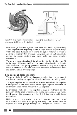
Figure 1.11: Open impeller (Reproduced by Figure 1.12: Recirculation with an open
permission of Goulds Pumps, ITT Industries) impeller
relatively high flow rate against a low head, and with a high efficiency.
These impellers are frequently found in large vertical propeller pumps
where the main function is to move as high a volume of water as
possible at relatively low pressures. Irrigation services and main intake
pumps for power stations and paper mills use these impellers
extensively.
The most common impeller designs have Specific Speed values that fall
in the range of 1500 to 3000, and are commonly referred to as Francis-
Vane impcllers. This group generally delivers a fairly wide range of
Flows at medium Heads and consequently is used extensively in water
and general service process pumps.
1.4.2 Open and closed impellers
The most distinctive difference between impellers in a process pump is
whether or not they are 'open' or 'closed'. Both types are widely used.
The open impeller has no shrouds on at least one side of the impeller.
Consequently, it can be said that, in the open impeller, the vanes are
easily visible from one or both sides of the impeller.
Recirculation with an open impeller design is restricted by the
proximity of the front of the impeller to the pump casing. In a typical
ANSI pump this clearance will be 0.015 ins. on a cold liquid
application.
Wider settings or excessive wear will increase the amount of
recirculation, and reduce the pump efficiency. This clearance can be
adjusted on most pumps through an arrangement located at the
:!!!!!
10 ..... , _ ....................... !!!!!!!~ ..............................................