
Page 26 -
P. 26
iiii .... ::::::::::::::::::::::::: .... Centrifugal Pumps
This load must be accommodated by the shaft and bearings, and much
has been discussed on this problem in recent years.
The resultant unbalanced load is at its maximum when the pump is run
at the shutoff condition. It gradually decreases as the flow rate
approaches the Best Efficiency Point (BEP). If the pump operates
beyond the B EP, the load increases again, but in the opposite direction
on the same plane. Examination of the resultant shaft deflection
problems has indicated that the radial plane on which the out-of-
balance load acts is approximately 60 ~ counterclockwise from the cut-
water of the volute.
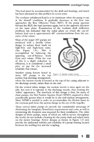
Most of the larger API pumps are
produced with a double volute
design to reduce these loads on
high-flow and high-head units.
(See Figure 1.4.) This is
accomplished by balancing the
opposing out-of- balance loads
from each volute. While the cost
of this is a slight reduction in
efficiency, it is considered a small
price to pay for the increased
reliability that ensues.
Another casing feature found in
many API pumps is the top Figure 1.4: Double volute casing
suction/top discharge arrangement,
where the suction nozzle is located at the top of the casing adjacent to
the discharge nozzle, rather than on the end.
On the vertical inline design, the suction nozzle is once again on the
side, but now it is opposite to the discharge nozzle, thus creating the
'inline' appearance. The drawback of this design is that, for many of
these pumps, the Net Positive Suction Head (NPSH) required is often
considerably greater than it would be in the end suction arrangement.
More NPSH is needed in order to accommodate the friction losses in
the tortuous path from the suction flange to the eye of the impeller.
These vertical inline pumps do provide the considerable advantage of
eliminating the baseplate/foundation requirements and costs, as well as
minimizing the footprint area required for their installation. The older
designs of inline pumps, many of which are still in service throughout
the world, do not include a bearing for the pump shaft and relied solely
on the motor bearings. Newer designs as shown in Figure 1.5 now
provide the additional stability and reliability of a pump bearing located
between the stuffing box and the coupling.
- ....... 5 m