
Page 25 -
P. 25
The Practical Pumping Handbook ~ ::::: - -: ::~c---~
Many of these more aggressive liquids can produce toxic fluid exposure
and vapors if they are allowed to leak out of a pump. For example,
vapor release is a common danger with hydrocarbons that vaporize at
atmospheric conditions or other chemicals that may be exposed to very
high operating temperatures. If a vapor release is exposed to a spark,
the vapor cloud may even explode or catch fire.
Consequently, in handling these liquids, we must be extremely aware of
much more than environmental damage and pumping efficiency. We
must also be very conscious about personal safety. Therefore, the choice
between the ANSI pump and the API pump must take into account the
specific fluid properties, as well as the operating conditions. The main
difference between these pumps is predominantly a result of the
differences in casing design.
1.3 Pump cases
Both pump styles have a radial split casing, and most smaller pump
cases employ a single volute design of the interior passages. This is
particularly evident with low-flow rates and lower specific speeds of the
impeller.
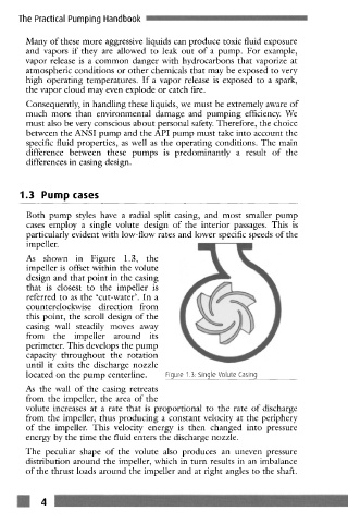
As shown in Figure 1.3, the
impeller is offset within the volute
design and that point in the casing
that is closest to the impeller is
referred to as the 'cut-water'. In a
counterclockwise direction from
this point, the scroll design of the
casing wall steadily moves away
from the impeller around its
perimeter. This develops the pump
capacity throughout the rotation
until it exits the discharge nozzle
located on the pump centerline. Figure 1.3. Single Volute Casing
As the wall of the casing retreats
from the impeller, the area of the
volute increases at a rate that is proportional to the rate of discharge
from the impeller, thus producing a constant velocity at the periphery
of the impeller. This velocity energy is then changed into pressure
energy by the time the fluid enters the discharge nozzle.
The peculiar shape of the volute also produccs an uneven pressure
distribution around the impeller, which in turn results in an imbalance
of the thrust loads around the impeller and at right angles to the shaft.
m 4 --