
Page 79 -
P. 79
The Practical Pumping Handbook . . . . . . .
4.4.1.6 Use a booster pump
Installed immediately upstream of the main pump, a booster pump
must be able to operate at the same flow rate, but usually at a lower
head, thus requiring less NPSH.
From this list of possibilities, you will note that there are specific
concerns connected with the first two options, while the remaining
ones require the installation of at least one new pump. Therefore to
stop cavitation in most instances, the only really practical solution is to
increase the NPSH available from the system.
4.4.2 NPSH available from the system
The NPSH Available from the System is relatively straightforward as it
consists of only four absolute values.
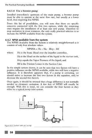
NPSHA = Hs + Ha- Hvp - Hf
where: Hs is the Static Head over the impeller centerline,
Ha is the Head on the surface of the liquid in the suction tank,
Hvp equals the Vapor Pressure of the liquid, and
Hf is the Friction Losses in the Suction Line.
In the simple system shown, it can be seen that two factors will have a
positive influence on the NPSH available, while two will have a negative
influence. It is therefore apparent that, if a pump is cavitating, we
should strive to increase the first two factors in the equation, and/or
decrease the second two factors.
Once again, it should be stressed that a huge difference is not normally
needed to eliminate cavitation. A few feet of NPSH will usually be
enough. With this is mind, we can consider the four factors as they
relate to a typical pump inlet system.
i Ha
Figure 4.4: Suction tank and pump
m 58