
Page 121 - The Toyota Way Fieldbook
P. 121
98 THE TOYOTA WAY FIELDBOOK
Complex Flow Situations
If we consider a different example with a higher degree of complexity, we can
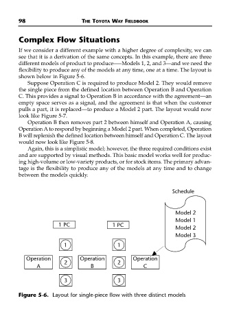
see that it is a derivation of the same concepts. In this example, there are three
different models of product to produce—–Models 1, 2, and 3—and we need the
flexibility to produce any of the models at any time, one at a time. The layout is
shown below in Figure 5-6.
Suppose Operation C is required to produce Model 2. They would remove
the single piece from the defined location between Operation B and Operation
C. This provides a signal to Operation B in accordance with the agreement—an
empty space serves as a signal, and the agreement is that when the customer
pulls a part, it is replaced—to produce a Model 2 part. The layout would now
look like Figure 5-7.
Operation B then removes part 2 between himself and Operation A, causing
Operation A to respond by beginning a Model 2 part. When completed, Operation
B will replenish the defined location between himself and Operation C. The layout
would now look like Figure 5-8.
Again, this is a simplistic model; however, the three required conditions exist
and are supported by visual methods. This basic model works well for produc-
ing high-volume or low-variety products, or for stock items. The primary advan-
tage is the flexibility to produce any of the models at any time and to change
between the models quickly.
Schedule
Model 2
Model 1
1 PC 1 PC
Model 2
Model 3
1 1
Operation Operation Operation
2 2
A B C
3 3
Figure 5-6. Layout for single-piece flow with three distinct models