
Page 214 - The Tribology Handbook
P. 214
B10 Cams and followers
Calculation of contact (Hertzian) stress tappet radius and 4-7 min for 1500-2540mm tappet rad-
ius). Alternatively the longitudinal tappet axis is tilted by
It is now necessary to calculate the Hertzian stresses a corresponding amount to the camshaft axis. The theore-
between the cam and tappet. Most tappets and cams can tical point contact extends into an elongated ellipse under
be classified into one of the forms shown in Figure 10.4. load to give a better contact zone than with the nominally
The appropriate formulae for the Hertzian stress are listed flat face.
below.
The following symbols and units are used:
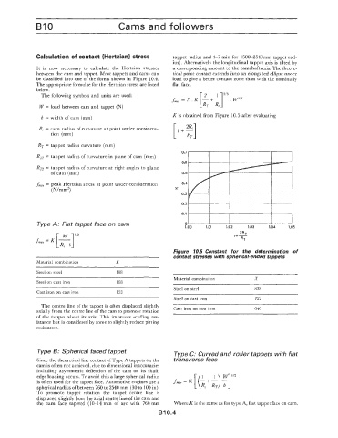
fm,, = X. K - +- . W1I3
W = load between cam and tappet (N) [iT :]2'3
b = width of cam (mm) K is obtained from Figure 10.5 after evaluating
R, = cam radius of curvature at point under considera- [I+?]
tion (mm)
RT = tappet radius curvature (mm)
0.7
R, = tappet radius of curvature in plane of cam (mm)
0.6
Rn = tappet radius of curvature at right angles to plane
of cam (mm) 0.5
fmnx = peak Hertzian stress at point under consideration 0.4
( N/mm2) Y
0.3
0.2
O.' 1.00 rrrrl3
Type A: Flat tappet face on cam 0 1.01 1.02 1.03 1.04 1.05
2R
l+C
RT
Figure 10.5 Constant for the determination of
contact stresses with spherical-ended tappets
Material combination K
Steel on steel 188
Material combination X
Steel on cast iron 168
Steel on steel 838
Cast iron on cast iron 153
Steel on cast iron 722
The centre line of the tappet is often displaced slightly
axially from the centre line of the cam to promote rotation Cast iron on cast iron 640
of the tappet about its axis. This improves scuffing res-
istance but is considered by some to slightly reduce pitting
resistance.
Type B: Spherical faced tappet Type C: Curved and roller tappets with flat
Since the theoretical line contact of Type A tappets on the tranSVerSe face
cam is often not achieved, due to dimensional inaccuracies
including asymmetric deflection of the cam on its shaft,
edge loading occurs. To avoid this a large spherical radius T]
is often used for the tappet face. Automotive engines use a fmm = K [(I I)
-t
spherical radius of between 760 to 2540 mm (30 to 100 in). Rc RT
To promote tappet rotation the tappet centre line is
displaced slightly from the axial centre line of the cam and
the cam face tapered (10-14 min of arc with 760 mm Where K is the same as for type A, flat tappet face on cam.
B10.4