
Page 212 - The Tribology Handbook
P. 212
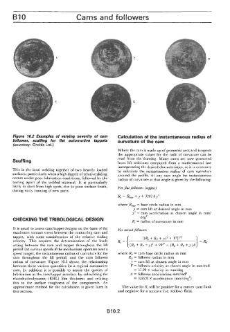
B10                           Cams and followers


                            1                                   2                                   3


                           4                                    5                                   6


                                                         Where the cam is made up of geometric arcs and tangents
                                                         the appropriate values for  the radii  of curvature can be
       Scuffing                                          read  from  the  drawing.  Many  cams  are  now  generated
                                                         from  lift  ordinates  computed  from  a  mathematical  law
                                                         incorporating the desired characteristics, so it is necessary
       This is  the local  welding together  of  two  heavily  loaded   to  calculate  the  instantaneous radius  of  cam  curvature
       surfaces, particularly when a high degree of relative sliding   around  the profile. At  any  cam  angle  the  instantaneous
       occurs under poor lubrication conditions,  followed by the   radius of curvature at that angle is given by the following:
       tearing  apart  of  the  welded  material.  It  is  particularly
       likely to start from high spots, due to poor surface finish,   For Jat  followers (tappets)
       during early running of new parts.
                                                         R, = Rb,,  +y + 3282.81"
                                                         where    = base circle radius in mm
                                                                y = cam lift at desired  angle in mm
                                                                y" = cam  acceleration  at  chosen  angle  in  mm/
                                                                    deg2
       CHECKING THE TRIBOLOGICAL DESIGN                         R, = radius of curvature in mm
       It is usual to assess cadtappet designs on the basis of the   For curved followers
       maximum contact stress between the contacting cam and
       tappet,  with  some  consideration  of  the  relative  sliding   Rc= {   [(Rb + RF  +y)* + v2]3'2   ).
       velocity.  This  requires  the  determination  of  the  loads
       acting  between  the  cam  and  tappet  throughout  the  lift   (Rb  RF  +y)2 4-  2v2 - (Rb + RF  +y)A
       period  (at various speeds if the mechanism operates over a
       speed range), the instantaneous radius of curvature for the   where Rb = cam base circle radius in mm
       cam  throughout  the  lift  period,  and  the  cam  follower   RF = follower radius in mm
       radius  of  curvature. Figure  10.3 shows the relationship   y  = cam lift at chosen angle in mm
       between  these various quantities for a typical automotive   V = follower velocity at chosen angle in mmhad
       cam.  In  addition  it  is  possible  to  assess  the  quality  of   = 57.29 X velocity in mm/deg
       lubrication at the camhappet interface by calculating the   A  = follower acceleration mm/rad2
       elastohydrodynamic (EHL) film  thickness  and  relating   = 3282.8  X  acceleration  (mm/deg2)
       this  to  the  surface  roughness  of  the  components.  An
       approximate method  for the  calculation  is  given later in   The value for R, will be positive for a convex cam flank
       this section.                                     and negative for a concave (i.e. hollow) flank.


                                                    B10.2