
Page 215 - The Tribology Handbook
P. 215
Cams and followers I310
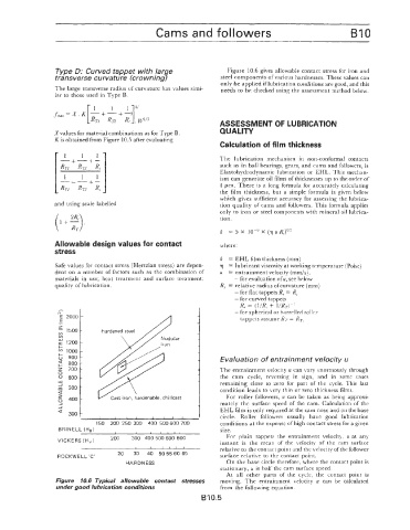
Type D: Curved tappet with !ar e Figure 10.6 gives allowable contact stress for iron and
transverse curvature (crown ing7 steel components of various hardnesses. These values can
only be applied if lubrication conditions are good, and this
The large transverse radius of curvature has values simi- needs to be checked using the assessment method below.
lar to those used in Type 3.
ASSESSMENT OF LUBRICATION
Xvalues for material combinations as for Type B. QUALITY
K is obtained from Figure 10.5 after evaluating
Calculation of film thickness
1
- 1 1 The lubrication mechanism in non-conformal contacts
+---C-
RTI RT2 __ such as in ball bearings, gears, and cams and followers, is
Rc
Elantohydrodynamic lubrication or EHL. This mechan-
1 1 1 ism can generate oil films of thicknesses up to the order of
-t - 1 pm. There is a long formula for accurately calculating
RT/ RE IPc the film thickness, but a simple formula is given below
which gives sufticient accuracy for assessing the lubrica-
and using scale labelled tion quality of cams and followers. This formula applies
(1 +:). only to iron or steel components with mineral oil lubrica-
tion.
h = 5 X X (q u R,)0.5
Allowable design values for contact where:
stress
h = EHL film thickness (mm)
Safe values for contact stress (Hertzian stress) are depen- q = lubricant viscosity at working temperature (Poise)
dent on a number of factors such as the combination of u = entrainment velocity (mm/s).
materials in use; heat treatment and surface treatment; - for evaluation of u, see below
quality of lubrication. R, = relative radius ofcurvature (nam)
- for flat tappets R, = R,
- for curved tappets
- R, = (l/R< + IIR&'
N - for spherical or barrelled roller
E 2000 tappets assume Rr = RT,
E
1
z
- 1500
(0
(I)
E 1200
1000
t; 900 Evaluation of entrainment velocity u
2 800
z 700 The entrainment velocity u can vary enormously through
0
0 600 the cam cycle, reversing in sign, and in some cases
u1 remaining close to zero for part of the cycle. This last
z 500 condition leads to very thin or zero thickness films.
-I
s mately the surface speed of the cam. Calculation of the
For roller followers, u can be taken as being approxi-
' 400
J EHL klm is only required at the cam nose and on the base
a 300 I
I I I I 1 1 1 1 circle. Roller followers usually have good lubrication
150 200 250 300 400 500 600 700 conditions at the expense of high contact stress for a given
BRINELL (HE) size.
~ For plain tappets the entrainment velocity, u at any
200 300 400 500 600 800
VICKERS (Hv ) instant is the mean of the velocity of the cam surface
/ , I I relative to the contact point and the velocity ofthe follower
20 30 40 505560 65
ROCKWELL 'C' surface relative to the contact point.
HARDNESS On the base circle therefore, where the contact point is
stationary, u is half the cam surface speed.
At all other parts of the cycle, the contact point is
Figure 10.6 Typical allowable contact stresses moving. The entrainment velocity u can be calculated
under good lubrication conditions from the following equation.
B 10.5