
Page 1011 - The Mechatronics Handbook
P. 1011
0066_frame_C34.fm Page 7 Wednesday, January 9, 2002 8:07 PM
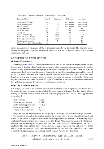
TABLE 34.1 Generated Parameters List and Setup of Their Limits
Parameter Name Symbol Dimension High Limit Low Limit
Stator outside diameter D e mm User optional User optional
Stator inside diameter D mm User optional User optional
Ideal iron length l i mm User optional User optional
Air gap induction Bδ T 0.5 1.0
Stator slot filling k dr1 — 0.6 0.75 (0.8)
Air gap size d mm 0.2 0.4
Stator current density σ 1 A mm −2 3.0 15.0
Rotor rod current density σ t A mm −2 2.0 6.0
Rotor ring current density σ k A mm −2 2.0 4.0
Teeth magnetic induction B z T 1.6 2.0
Slot number per pole and stator phase q 1 — 2.0 5.0
motor characteristics) using some of the optimization methods, was developed. The stochastic evolu-
tionary method genetic algorithm was selected, because it searches the whole state space of all possible
solution in a best way.
Description of a Solved Problem
Generated Parameters
The values given in Table 34.1 are recommended only, and, for the motors of outputs below 200 kW,
they are mostly limiting values. Varying the parameter values or substituting one parameter for another
is possible only by intervention in the program source text. Diameter limits D e and D from the input file
are considered only in the case that a motor design without regard to standardized axis height is required.
In the case that standardized axis height is entered, these limits are calculated. Limits of an ideal rotor
length are appropriate to enter as narrow as possible for faster convergence to a limit. But this is not a
required condition. Generally, the lower the range of individual parameters, the faster the convergence
to a global minimum, and the number of local minimums is lower.
Objective (Criterion) Function
It is not just the form of the objective function, but also the selection of optimized parameters that is
important for good optimization results. Selected parameters must sufficiently describe a quality solution
to the given problem. In the case of an induction motor design optimization task, the following parameters
were selected:
3
Motor volume V [dm ]
Motor temperature rise ϑ n [K]
Motor nominal power factor cos ϕ n [−]
Motor nominal efficiency η n [−]
Torque overload capacity m pn [−]
These parameters are most important for the quality of the design and describe the design sufficiently.
The total error is based on the relation given in Eq. (34.1), a sum of individual partial errors of each
controlled parameter. If we put more emphasis on some parameter, we increase a corresponding weight
coefficient, thus achieving its improvement in the final design. At the same time, values of other param-
eters will decrease. Finding an optimal setup of gain coefficients is one of the most important and difficult
problems. The term “optimal setup” means that the designed motor has the highest power factor,
efficiency, and torque overload capacity values at the minimal volume and simultaneously does not exceed
a permitted temperature rise for a selected insulation class. We have the relationship
(
⋅
(
(
(
(
(
e GR i ) = abs kV V) + abs kJ 0.89J d – J n )) + abs k cos 1 – cos j n ))
j
(
(
(
+ abs kh 1 h n )) + abs k mp m p + 1 m pn )) (34.1)
(
–
–
©2002 CRC Press LLC