
Page 1022 - The Mechatronics Handbook
P. 1022
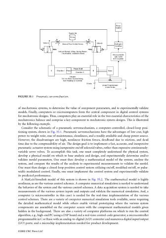
FIGURE 35.1  Pneumatic servomechanism.


                                 of mechatronic systems, to determine the value of component parameters, and to experimentally validate
                                 models. Finally, computers or microcomputers form the central component in digital control systems
                                 for mechatronic designs. Thus, computers play an essential role in the two essential characteristics of the
                                 mechatronics balance and comprise a key component to mechatronic system designs. This is illustrated
                                 by the following example.
                                   Consider the schematic of a pneumatic servomechanism, a computer-controlled, closed-loop posi-
                                 tioning system, shown in Fig. 35.1. Pneumatic servomechanisms have the advantages of low cost, high
                                 power-to-weight ratio, ease of maintenance, cleanliness, and a readily-available and cheap power source.
                                 However, the disadvantages are high, nonlinear friction forces, deadband due to stiction, and dead
                                 time due to the compressibility of air. The design goal is to implement a fast, accurate, and inexpensive
                                 pneumatic-actuator system using inexpensive on/off solenoid valves, rather than expensive continuously-
                                 variable servo valves.  To accomplish this task, one must completely understand the physical system,
                                 develop a physical model on which to base analysis and design, and experimentally determine and/or
                                 validate model parameters. One must then develop a mathematical model of the system, analyze the
                                 system, and compare the results of the analysis to experimental measurements to validate the model.
                                 One must then design a closed-loop position control system utilizing on/off, modified on/off, or pulse-
                                 width modulated control. Finally, one must implement the control system and experimentally validate
                                 its predicted performance.
                                   A MatLab/Simulink model of this system is shown in Fig. 35.2.  The mathematical model is highly
                                 nonlinear, as are the various control schemes. A computer numerical simulation is needed to understand
                                 the behavior of the system and the various control schemes. A data acquisition system is needed to take
                                 measurements of the various system inputs and outputs and validate the numerical simulation. And, a
                                 computer (a microcontroller in this case) is needed for the real-time implementation of the various
                                 control schemes. There are a variety of computer numerical simulation tools available, some requiring
                                 the detailed mathematical model while others enable virtual prototyping where the various system
                                 components are assembled on the computer screen with the component mathematical models given
                                 hidden in the background. There are also a variety of computer platforms on which to run the control
                                 algorithm, e.g., high-end PC using a DSP board and a real-time control-code generator; a microcontroller
                                 programmable in C or Basic with an analog-to-digital (A/D) converter and numerous digital input/output
                                 (I/O) ports; and a microchip implementation needed for product development.

                                 ©2002 CRC Press LLC