
Page 1025 - The Mechatronics Handbook
P. 1025
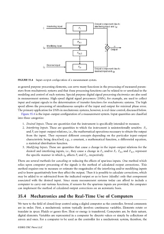
FIGURE 35.4  Input–output configuration of a measurement system.

                                 as general purpose processing elements, can serve many functions in the processing of measured param-
                                 eters from mechatronic systems and that these processing functions can be related to or unrelated to the
                                 modeling and control of such systems. Special purpose digital signal processing electronics are also used
                                 in measurement systems. High-speed digital signal processors (DSPs), for example, are used to collect
                                 input and output signals in the determination of transfer functions for mechatronic systems. The high
                                 speed allows the processing of simultaneous samples of the input and output for minimal phase error.
                                 The primary application for DSPs in mechatronic systems, however, is real-time control, discussed below.
                                   Figure 35.4 is the input–output configuration of a measurement system. Input quantities are classified
                                 into three categories:
                                    1. Desired Inputs. These are quantities that the instrument is specifically intended to measure.
                                    2. Interfering Inputs. These are quantities to which the instrument is unintentionally sensitive.  F D
                                       and F I  are input–output relations, i.e., the mathematical operations necessary to obtain the output
                                       from the input.  They represent different concepts depending on the particular input–output
                                       characteristic being described, e.g., a constant, a mathematical function, a differential equation,
                                       a statistical distribution function.
                                    3. Modifying Inputs. These are quantities that cause a change in the input–output relations for the
                                       desired and interfering inputs, i.e., they cause a change in F D  and/or F I . F M,I  and F M,D  represent
                                       the specific manner in which i M  affects F I  and F D , respectively.
                                 There are several methods for canceling or reducing the effects of spurious inputs. One method which
                                 relies upon computer processing of the signals is the method of calculated output corrections.  This
                                 method requires one to measure or estimate the magnitudes of the interfering and/or modifying inputs
                                 and to know quantitatively how they affect the output. Then it is possible to calculate corrections, which
                                 may be added to or subtracted from the indicated output so as to leave (ideally) only that component
                                 associated with the desired input.  Since many measurement systems today can afford to include a
                                 computer to carry out various functions, if sensors for the spurious inputs are provided, the computer
                                 can implement the method of calculated output corrections on an automatic basis.

                                 35.4 Mechatronics and the Real-Time Use of Computers

                                 We turn to the field of closed-loop control using a digital computer as the controller. Several comments
                                 are in order. First, a mechatronic system typically involves continuous variables. Elements rotate or
                                 translate in space. Fluids or gasses flow. Heat or energy is transferred. Computers are, by their nature,
                                 digital elements. Variables are represented in a computer by discrete values or simply by collections of
                                 zeroes and ones. For a computer to be used as the controller for a mechatronic system, therefore, the

                                 ©2002 CRC Press LLC