
Page 1159 - The Mechatronics Handbook
P. 1159
counted as a rising or falling edge. Isolation is another type of signal conditioning that separates the
measurement hardware circuitry from the signal being measured. This is done to remove large differences
in electric potential between the measurement hardware and the signal, and it protects the measurement
hardware from damage, given a large surge in voltage or current.
The heart of a data acquisition device is a digital-to-analog converter (DAC), an analog-to-digital
converter (ADC), or some combination of the two. An ADC has a finite list of values which represents
voltages. The purpose of the ADC is to select a value from this list, which is closest to an actual voltage
at a specified time. The value is then transferred in binary format to a computer. Alternatively, a DAC
can produce an analog voltage from a list of binary values. The voltage generated by a basic DAC stays
the same until it receives another value from the computer. In order to acquire and produce analog
waveforms, the DAC and ADC must activate at precise intervals. Consequently, measurement hardware
has timing circuitry to produce a pulse train of a constant frequency to control the ADC and DAC.
The data that is transferred from the ADC and to the DAC travels to the computer over a bus. A bus
is a group of electrical conductors that transfer information inside a computer. Some common examples
of a bus are PCI and USB. The bus can carry both control information and binary measurement data to
and from measurement hardware. One of the most important considerations in selecting a bus is bus
transfer rate, usually expressed in megabytes per second (Mbytes/s). A single analog value could require
less than 1 byte or as much as 4 bytes, depending on the type of measurement hardware. The bus is shared
among multiple devices, so data acquisition devices often have on-board memory to serve as a holding
place for data when the bus is not available. In very fast data acquisition routines, the memory can hold
all the data, and at the end of the acquisition, all the data can be transferred to the computer for processing.
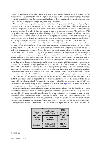
When data is acquired at high speeds on multiple channels, it is often important to understand the
phase relationship from one signal to the next. If the signals are generated or acquired on multiple data
acquisition devices, there are a number of ways to synchronize the systems and preserve relative phase
relationships. One way is to share the ADC and DAC clock between the data acquisition devices. The real-
time system integration bus (RTSI) is a bus that can connect multiple devices together to share timing
circuitry among multiple devices. Phase-lock looping (PLL) is a more sophisticated synchronization
method. A reference signal is supplied to all the data acquisition devices, and the internal clocks stay in
phase with the reference signal. Consequently, the phase relationship can be reserved even if different
measurement hardware is using different sampling or update speeds. Figure 44.2 is a diagram showing
the components of a typical data acquisition hardware.
The difference between an actual analog voltage and the closest voltage from the list of binary values
is called the quantization error. In a perfect digitizing measurement system free of noise, the quantization
error would solely explain any difference between the actual voltage and the measured voltage. No mea-
surement hardware and no environment, however, are perfect. The accuracy of an instrument describes
the amount of uncertainty when considering quantization error, unavoidable system noise, and hardware
imperfections. Accuracy is sometimes confused with precision. Precision refers to the amount of deviation
in multiple measurements connected to a constant and level signal source. Even if an instrument is
FIGURE 44.2
©2002 CRC Press LLC