
Page 1162 - The Mechatronics Handbook
P. 1162
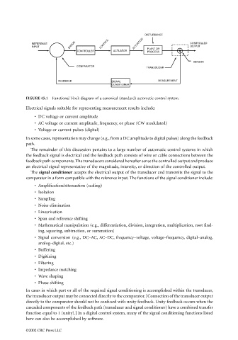
DISTURBANCE
                                                    ERROR
                                    REFERENCE                    CONTROL       ACTUATION               CONTROLLED
                                    INPUT                                            PLANT OR          OUTPUT
                                                       CONTROLLER     ACTUATOR       PROCESS
                                                                                                        SENSOR
                                                       COMPARATOR
                                                                                    TRANSDUCER

                                               FEEDBACK               SIGNAL             MEASUREMENT
                                                                      CONDITIONER


                                 FIGURE 45.1  Functional block diagram of a canonical (standard) automatic control system.
                                 Electrical signals suitable for representing measurement results include:
                                     • DC voltage or current amplitude
                                     • AC voltage or current amplitude, frequency, or phase (CW modulated)
                                     • Voltage or current pulses (digital)
                                 In some cases, representation may change (e.g., from a DC amplitude to digital pulses) along the feedback
                                 path.
                                   The remainder of this discussion pertains to a large number of automatic control systems in which
                                 the feedback signal is electrical and the feedback path consists of wire or cable connections between the
                                 feedback path components. The transducers considered hereafter sense the controlled output and produce
                                 an electrical signal representative of the magnitude, intensity, or direction of the controlled output.
                                   The signal conditioner accepts the electrical output of the transducer and transmits the signal to the
                                 comparator in a form compatible with the reference input. The functions of the signal conditioner include:
                                     • Amplification/attenuation (scaling)
                                     • Isolation
                                     • Sampling
                                     • Noise elimination
                                     • Linearization
                                     • Span and reference shifting
                                     • Mathematical manipulation (e.g., differentiation, division, integration, multiplication, root find-
                                       ing, squaring, subtraction, or summation)
                                     • Signal conversion (e.g., DC–AC, AC–DC, frequency–voltage, voltage–frequency, digital–analog,
                                       analog–digital, etc.)
                                     • Buffering
                                     • Digitizing
                                     • Filtering
                                     • Impedance matching
                                     • Wave shaping
                                     • Phase shifting
                                 In cases in which part or all of the required signal conditioning is accomplished within the transducer,
                                 the transducer output may be connected directly to the comparator. [Connection of the transducer output
                                 directly to the comparator should not be confused with unity feedback. Unity feedback occurs when the
                                 cascaded components of the feedback path (transducer and signal conditioner) have a combined transfer
                                 function equal to 1 (unity).] In a digital control system, many of the signal conditioning functions listed
                                 here can also be accomplished by software.

                                 ©2002 CRC Press LLC