
Page 1165 - The Mechatronics Handbook
P. 1165
DC SOURCE
INPUT
RESISTANCE ELEMENT θ
WIPER
x
INPUT
OUTPUT
OUTPUT DC SOURCE
(a) RECTILINEAR ROTARY
AC
SOURCE
MAGNETIC
CORE
INPUT
SHAFT
AC
SOURCE θ
INPUT
MAGNETIC
CORE INPUT
x
INPUT
SHAFT
OUTPUT OUTPUT
(b)
RECTILINEAR (LVDT) ROTARY (RVDT)
θ 2 θ
1
AC ERROR
SOURCE SIGNAL
CONTROLLED ANGLE REFERENCE ANGLE
(SYSTEM OUTPUT) (SYSTEM INPUT)
(c)
CONTROL TRANSMITTER CONTROL TRANSFORMER
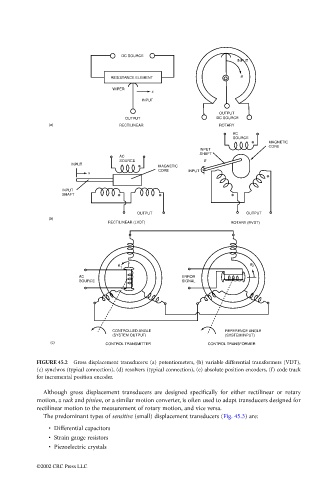
FIGURE 45.2 Gross displacement transducers: (a) potentiometers, (b) variable differential transformers (VDT),
(c) synchros (typical connection), (d) resolvers (typical connection), (e) absolute position encoders, (f) code track
for incremental position encoder.
Although gross displacement transducers are designed specifically for either rectilinear or rotary
motion, a rack and pinion, or a similar motion converter, is often used to adapt transducers designed for
rectilinear motion to the measurement of rotary motion, and vice versa.
The predominant types of sensitive (small) displacement transducers (Fig. 45.3) are:
• Differential capacitors
• Strain gauge resistors
• Piezoelectric crystals
©2002 CRC Press LLC