
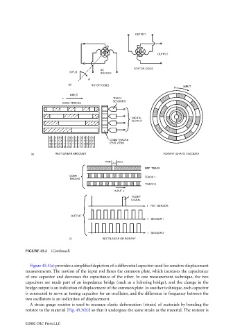
Page 1166 - The Mechatronics Handbook
P. 1166
OUTPUT


                                                                                           OUTPUT


                                                                                STATOR COILS
                                                                  AC
                                                    INPUT         SOURCE
                                                            θ
                                                    (d)       ROTOR COILS
                                                                                                  θ   INPUT
                                                     INPUT
                                                 x                     TRACK
                                                                       SENSORS
                                                 CODE TRACKS


                                                                               DIGITAL
                                                                               OUTPUT


                                            0  1  1  0  0  1  1  0  0  1  1  0  0  1  1  0
                                            0  0  1  1  1  1  0  0  0  0  1  1  1  1  0  0  CODE TRACKS
                                            0  0  0  0  1  1  1  1  1  1  1  1  0  0  0  0  (END VIEW)
                                            0  0  0  0  0  0  0  0  1  1  1  1  1  1  1  1
                                    (e)       RECTILINEAR ENCODER                            ROTARY (SHAFT) ENCODER

                                                                       ∆x
                                                                                     REF. TRACK
                                                    CODE                             TRACK 1
                                                    TRACKS
                                                                                     TRACK 2
                                                                        INPUT x
                                                                               "HOME"
                                                                               SIGNAL
                                                                                      t  REF. SENSOR

                                                     OUTPUT
                                                                                      t  SENSOR 1


                                                                                      t  SENSOR 2
                                                    (f)            RECTILINEAR OR ROTARY

                                 FIGURE 45.2  (Continued)


                                   Figure 45.3(a) provides a simplified depiction of a differential capacitor used for sensitive displacement
                                 measurements. The motion of the input rod flexes the common plate, which increases the capacitance
                                 of one capacitor and decreases the capacitance of the other. In one measurement technique, the two
                                 capacitors are made part of an impedance bridge (such as a Schering bridge), and the change in the
                                 bridge output is an indication of displacement of the common plate. In another technique, each capacitor
                                 is connected to serve as tuning capacitor for an oscillator, and the difference in frequency between the
                                 two oscillators is an indication of displacement.
                                   A strain gauge resistor is used to measure elastic deformation (strain) of materials by bonding the
                                 resistor to the material [Fig. 45.3(b)] so that it undergoes the same strain as the material. The resistor is


                                 ©2002 CRC Press LLC