
Page 184 - The Mechatronics Handbook
P. 184
0066_frame_C10 Page 4 Wednesday, January 9, 2002 4:10 PM
Discharge Coefficient
Spool Position
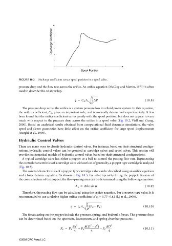
FIGURE 10.2 Discharge coefficient versus spool position in a spool valve.
pressure drop and the flow rate across the orifice. An orifice equation (McCloy and Martin, 1973) is often
used to describe this relationship.
q = C d A o 2 (10.8)
---∆P
r
The pressure drop across the orifice is a system pressure loss in a fluid power system. In this equation,
the orifice coefficient, C d , plays an important role, and is normally determined experimentally. It has
been found that the orifice coefficient varies greatly with the spool position, but does not appear to vary
much with respect to the pressure drop across the orifice in a spool valve (Fig. 10.2, Viall and Zhang,
2000). Based on analytical results obtained from computational fluid dynamics simulations, the valve
spool and sleeve geometries have little effect on the orifice coefficient for large spool displacements
(Borghi et al., 1998).
Hydraulic Control Valves
There are many ways to classify hydraulic control valves. For instance, based on their structural configu-
rations, hydraulic control valves can be grouped as cartridge valves and spool valves. This section will
provide mathematical models of hydraulic control valves based on their structural configurations.
A typical cartridge valve has either a poppet or a ball to control the passing flow rate. Representing
the control characteristics of a cartridge valve without loss of generality, a poppet type cartridge is analyzed
(Fig. 10.3).
The control characteristics of a poppet type cartridge valve can be described using an orifice equation
and a force balance equation. As shown in Fig. 10.3, the valve opens by lifting the poppet. Because of
the cone structure of the poppet, the flow-passing area can be determined using the following equation:
A x = pdx sin a (10.9)
Therefore, the passing flow can be calculated using the orifice equation. For a poppet type valve, it is
recommended to use a relative higher orifice coefficient of c d = 0.77∼0.82 (Li et al., 2000).
--- P B –(
q = c d A x 2 P A ) (10.10)
r
The forces acting on the poppet include the pressure, spring, and hydraulic forces. The pressure force
can be determined based on the upstream, downstream, and spring chamber pressures.
2
2 ( 2 d ) 2
-------- +
F P = P A pd P B p D – P C pD (10.11)
---------
------------------------- –
4 4 4
©2002 CRC Press LLC