
Page 190 - The Mechatronics Handbook
P. 190
Based on the stability criterion for a second-order system, it should satisfy
1 2z
----- 2s + ------ s + 1 = 0 (10.32)
2
w n
w n
The speed control coefficient, K s , is the gain between the control signal current and the cylinder speed.
A higher gain can increase the system sensitivity in speed control.
E/H System Feedforward-Plus-PID Control
Equation (10.31) indicates that the speed control of a hydraulic cylinder is a third-order system. Its
dynamic behaviors are affected by spool valve characteristics, system pressure, and cylinder size. There-
fore, it is a challenging job to realize accurate and smooth speed control on a hydraulic cylinder. A
feedforward plus proportional integral derivative (FPID) controller has proven capable of achieving high-
speed control performance of a hydraulic cylinder (Zhang, 1999).
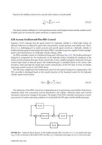
An FPID controller consists of a feedforward loop and a PID loop (Fig. 10.5). The feedforward loop is
designed to compensate for the nonlinearity of the hydraulic system, including the deadband of the
system and the nonlinear flow gain of the control valve. It uses a feedforward gain to determine the basic
control input based on demand speed. This feedforward gain is scheduled based on the inverse valve
transform, which provides the steady-state control characteristics of the E/H valve in terms of cylinder
speed and control-current to valve PWM driver.
The PID loop complements the feedforward control via the speed tracking error compensation. The
PID controller is developed based on the transfer function of the linearized system for the hydraulic
cylinder speed control system.
Ê K I ˆ
-----
G s() = K P + + K D s (10.33)
Ë s ¯
The robustness of the FPID control was evaluated based on its performance and stability. Performance
robustness deals with unexpected external disturbances and stability robustness deals with internal
structural or parametric changes in the system. The design of this FPID controller was based on a worst-
case scenario of system operating conditions in tuning both the PID gains and the feedforward gain.
G (s)
F
G PID (s) G (s)
H
H (s)
C
FIGURE 10.5 Schematic block diagram of the feedforward-plus-PID controller. G F (s) is the feedforward gain,
G PID (s) is the overall gain of the feedback PID controller, G H (s) is hydraulic system gain, and H C (s) is the sensor gain.
©2002 CRC Press LLC