Page 238 - The Mechatronics Handbook
P. 238

0066_frame_C12  Page 8  Wednesday, January 9, 2002  4:22 PM


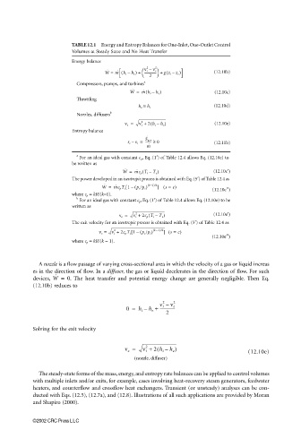
                                    TABLE 12.1  Energy and Entropy Balances for One-Inlet, One-Outlet Control
                                    Volumes at Steady State and No Heat Transfer
                                    Energy balance
                                                                2
                                                             2  v e
                                                            v i –
                                               ˙
                                               W =  m ˙ ( h i –  h e ) +    --------------- +  gz i –(  z e )  (12.10b)
                                                                
                                                              2
                                                            a
                                     Compressors, pumps, and turbines
                                                       W =  m ˙ h i –  h e )       (12.10c)
                                                            (
                                                        ˙
                                     Throttling
                                                          h e ≅  h i               (12.10d)
                                     Nozzles, diffusers b
                                                              (
                                                     v e =  v i +  2 h i –  h e )  (12.10e)
                                                           2
                                    Entropy balance
                                                             ˙
                                                            S gen
                                                      s e –  s i =  -------- ≥  0  (12.11b)
                                                             m ˙
                                     a
                                       For an ideal gas with constant c p , Eq. (1′) of Table 12.4 allows Eq. (12.10c) to
                                    be written as
                                                     ˙
                                                     W =  m ˙ c p T i –(  T e )    (12.10c′)
                                    The power developed in an isentropic process is obtained with Eq. (5′) of Table 12.4 as
                                              ˙
                                              W =  m ˙ c p T i 1 –[  ( p e /p i ) ( k−1)/k ] ( s = c)  (12.10c′′)
                                    where c p  = kR/(k−1).
                                     b
                                       For an ideal gas with constant c p , Eq. (1′) of Table 12.4 allows Eq. (12.10e) to be
                                    written as
                                                             (
                                                         2
                                                   v e =  v i +  2c p T i –  T e )  (12.10e′)
                                    The exit velocity for an isentropic process is obtained with Eq. (5′) of Table 12.4 as
                                                                –
                                                       [
                                                  2
                                             v e =  v i +  2c p T i 1 –  ( p e /p i ) ( k 1)/k ] ( s =  c)
                                                                                   (12.10e′′)
                                    where c p  = kR/(k − 1).
                         A nozzle is a flow passage of varying cross-sectional area in which the velocity of a gas or liquid increas
                       es in the direction of flow. In a diffuser, the gas or liquid decelerates in the direction of flow. For such
                       devices,  W =  0 .  The heat transfer and potential energy change are generally negligible. Then Eq.
                              ˙
                       (12.10b) reduces to
                                                                  2   2
                                                                 v i –  v e
                                                      0 =  h i –  h e +  ---------------
                                                                   2
                       Solving for the exit velocity

                                                     v e =  v i +  2 h i –  h e )
                                                                (
                                                            2
                                                                                               (12.10e)
                                                         ( nozzle, diffuser)
                         The steady-state forms of the mass, energy, and entropy rate balances can be applied to control volumes
                       with multiple inlets and/or exits, for example, cases involving heat-recovery steam generators, feedwater
                       heaters, and counterflow and crossflow heat exchangers. Transient (or unsteady) analyses can be con-
                       ducted with Eqs. (12.5), (12.7a), and (12.8). Illustrations of all such applications are provided by Moran
                       and Shapiro (2000).


                       ©2002 CRC Press LLC
   233   234   235   236   237   238   239   240   241   242   243