Page 261 - The Mechatronics Handbook
P. 261

0066_frame_C12  Page 26  Wednesday, January 9, 2002  4:22 PM


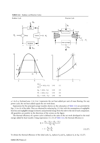
                        TABLE 12.6  Rankine and Brayton Cycles
                        Rankine Cycle                                        Brayton Cycle


                                                  ˙
                                                 W p 
                                                    =  m ˙ h 2 –(  h 1 )  (>0)  (1)
                                                 W c 
                                                  ˙
                                                       (
                                                  ˙
                                                 Q in =  m ˙ h 3 –  h 2 )  (>0)  (2)
                                                       (
                                                  ˙
                                                 W t =  m ˙ h 3 –  h 4 )  (>0)  (3)
                                                 Q out =  m ˙ h 1 –  h 4 )  (>0)  (4)
                                                  ˙
                                                        (
                       a-1-4s-b-a. Enclosed area 1-2s-3-4s-1 represents the net heat added per unit of mass flowing. For any
                       power cycle, the net heat added equals the net work done.
                         Expressions for the principal energy transfers shown on the schematics of Table 12.6 are provided by
                       Eqs. (1) to (4) of the table. They are obtained by reducing Eq. (12.10a) with the assumptions of negligible
                       heat loss and negligible changes in kinetic and potential energy from the inlet to the exit of each component.
                       All quantities are positive in the directions of the arrows on the figure.
                         The thermal efficiency of a power cycle is defined as the ratio of the net work developed to the total
                       energy added by heat transfer. Using expressions (1)–(3) of Table 12.6, the thermal efficiency is
                                                        ( h 3 –  h 4 ) ( h 2 –  h 1 )
                                                                –
                                                    h =  -----------------------------------------------
                                                              h 3 –  h 2
                                                      =  1 –  h 4 –  h 1                        (12.27)
                                                           ----------------
                                                           h 3 –  h 2

                       To obtain the thermal efficiency of the ideal cycle, h 2s  replaces h 2  and h 4s  replaces h 4  in Eq. (12.27).

                       ©2002 CRC Press LLC
   256   257   258   259   260   261   262   263   264   265   266