
Page 291 - The Mechatronics Handbook
P. 291
into three horizontal and six vertical strips, and contains 18 sections, each identified by ordered pairs of
characters, such as (E, P) or (O, C).
In each ordered pair, the first entry is a letter chosen from the bounded electromagnetic system set
M = { E, O, I}
The second entry is a letter chosen from the geometric set
G = { P, S, T, N, C, A}
That is, for electromagnetic microdevices, the electromagnetic system–geometric set is
M × G = ( { E, F ), E, S), E, T),..., I, N),(I, C), I, A)}
(
(
(
(
In general, we have
M × G = ( { m, g ) : m ∈ M and ∈ G }
g
Other categorization can be applied. For example, single-, two-, three-, and multi-phase microdevices
are classified using a phase classifier
H = { h : h ∈ H}
Therefore, Y × M × G × H = {(y, m, g, h) : y ∈ Y, m ∈ M, g ∈ G and h ∈ H}
Topology (radial or axial), permanent magnets shaping (strip, arc, disk, rectangular, triangular, or
other shapes), permanent magnet characteristics (BH demagnetization curve, energy product, hysterisis
minor loop), commutation, emf distribution, cooling, power, torque, size, torque-speed characteristics,
as well as other distinct features of microdevices can be easily classified.
That is, the devised electromagnetic microdevices can be classified by an N-tuple as
{microdevice type, electromagnetic system, geometry, topology, phase, winding, connection, cooling}.
Using the classifier, which is given in Table 14.1 in terms of electromagnetic system–geometry, the
designer can classify the existing motion microdevices as well as synthesize novel high-performance
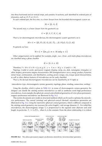
microdevices. As an example, the spherical, conical, and cylindrical geometries of a two-phase permanent-
magnet synchronous microdevice are illustrated in Fig. 14.2.
This section documents new results in structural synthesis which can be used to optimize the microde-
vice performance. The conical (existing) and spherical-conical (devised) microdevice geometries are
illustrated in Fig. 14.2. Using the innovative spherical-conical geometry, which is different compared to
the existing conical geometry, one increases the active length L r and average diameter D r . For radial flux
microdevices, the electromagnetic torque T e is proportional to the squared rotor diameter and axial
2
length. In particular, T e = k T D r L r , where k T is the constant. From the above relationship, it is evident
Endless Electromagnetic System Conical Geometry Cylindrical Geometry
Spherical-Conical
Spherical Geometry Assymetrical Geometry
Geometry
N as bs N as bs bs N as bs N
as bs N bs N as as bs
as N bs N as bs N as bs N
as
Stator Rotor Stator Stator Stator Rotor Stator Rotor Stator Rotor
Stator
Rotor
Stator
S
S
S
S
S
Rotor S Stator S Stator S
S Stator S Stator Rotor Rotor Stator
Rotor
Rotor Rotor
FIGURE 14.2 Two-phase permanent-magnet synchronous microdevice (micromachine) geometry.
©2002 CRC Press LLC