
Page 300 - The Mechatronics Handbook
P. 300
0066_frame_C14.fm Page 14 Wednesday, January 9, 2002 1:49 PM
where i is the current in the phase microwinding (supplied by the IC), R in st is the inner stator radius, L
is the inductance, P is the number of poles, and g e is the equivalent gap, which includes the airgap and
radial thickness of the permanent magnet.
Denoting the number of turns per phase as N S , the magnetomotive force is
mmf = iN S Pθ r
-------- cos
P
The simplified expression for the electromagnetic torque for radial topology brushless micromachines
is
T = 1
--PB ag i s N S L r D r
2
where B ag is the air gap flux density, B ag = (µiN S /2Pg e )cosPθ r , i s is the total current, L r is the active length
(rotor axial length), and D r is the outside rotor diameter.
The axial topology brushless micromachines can be designed and fabricated. The electromagnetic
torque is given as
T = k ax B ag i s N S D a 2
where k ax is the nonlinear coefficient, which is found in terms of active conductors and thin-film permanent
magnet length; and D a is the equivalent diameter, which is a function of windings and permanent-magnet
topography.
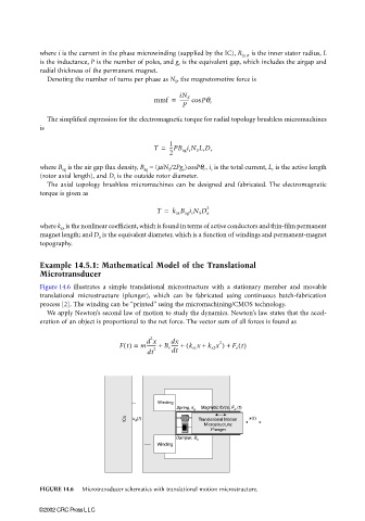
Example 14.5.1: Mathematical Model of the Translational
Microtransducer
Figure 14.6 illustrates a simple translational microstructure with a stationary member and movable
translational microstructure (plunger), which can be fabricated using continuous batch-fabrication
process [2]. The winding can be ‘‘printed” using the micromachining/CMOS technology.
We apply Newton’s second law of motion to study the dynamics. Newton’s law states that the accel-
eration of an object is proportional to the net force. The vector sum of all forces is found as
2
d x
------ +
Ft() = m-------- + B v dx ( k s1 x + k s2 x ) + F e t()
2
dt 2 dt
Winding
Spring, k Magnetic force, F (t)
s e
ICs u (t) Translational Motion x(t)
a
Microstructure:
Plunger
Damper, B v
Winding
FIGURE 14.6 Microtransducer schematics with translational motion microstructure.
©2002 CRC Press LLC