Page 303 - The Mechatronics Handbook
P. 303

0066_frame_C14.fm  Page 17  Wednesday, January 9, 2002  1:49 PM


                                                  L m
                                                L m max
                                                       L  m
                                                  L m
                                                       L  m
                                                L m min

                                                   0              3    2    r
                                                                  2
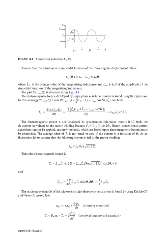
                       FIGURE 14.8  Magnetizing inductance L m (θ r ).


                         Assume that this variation is a sinusoidal function of the rotor angular displacement. Then,

                                                    L m θ r =  L m –  L ∆m cos  2θ r
                                                      ()
                               is the average value of the magnetizing inductance and L ∆m  is half of the amplitude of the
                       where  L m
                       sinusoidal variation of the magnetizing inductance.
                         The plot for L m (θ r ) is documented in Fig. 14.8.
                         The electromagnetic torque, developed by single-phase reluctance motors is found using the expression
                       for the coenergy W c (i as , θ r ). From W c (i as , θ r ) = --(L ls +  L m –  L ∆m cos 2θ r )i as ,  one finds
                                                          1
                                                                              2
                                                          2
                                                     [
                                                         (
                                                      1 2
                                        ∂W c i as ,θ r )  ∂ --i as L ls +  L m – L ∆m cos2θ r )]
                                           (
                                                                                   2
                                   T e =  --------------------------- =  ---------------------------------------------------------------------- =  L ∆m i as sin  2θ r
                                                      2
                                           ∂θ r                ∂θ r
                         The electromagnetic torque is not developed by synchronous reluctance motors if IC feeds the
                       dc current or voltage to the motor winding because T e =  L ∆m i as  sin2θ r .  Hence, conventional control
                                                                        2
                       algorithms cannot be applied, and new methods, which are based upon electromagnetic features must
                       be researched. The average value of  T e  is not equal to zero if the current is a function of  θ r . As  an
                       illustration, let us assume that the following current is fed to the motor winding:
                                                      i as =  i M  Re(  sin 2θ r )
                         Then, the electromagnetic torque is


                                                                          2
                                                               (
                                         T e =  L ∆m i as sin 2θ r =  L ∆m i M Re sin 2θ r )  sin2θ r ≠  0
                                                              2
                                                 2
                       and
                                              T eav =  1 ∫ π L ∆m i as  sin2θ r dθ r =  1 --L ∆m i M
                                                                             2
                                                           2
                                                    ---
                                                    π 0                 4
                         The mathematical model of the microscale single-phase reluctance motor is found by using Kirchhoff’s
                       and Newton’s second laws

                                              u as =  r s i as +  dψ as  (circuitry equation)
                                                        -----------
                                                         dt
                                                       2
                                                      d θ r
                                       T e –  B m ω r – T L =  J----------  ( torsional-mechanical equation)
                                                        2
                                                       dt

                       ©2002 CRC Press LLC
   298   299   300   301   302   303   304   305   306   307   308