Page 308 - The Mechatronics Handbook
P. 308

0066_frame_C14.fm  Page 22  Wednesday, January 9, 2002  1:50 PM


                                              1
                                             0.8
                                             0.6
                                             0.4
                                             0.2
                                              0
                                            -0.2
                                            -0.4
                                            -0.6
                                            -0.8
                                              -1
                                               0   1  2  3  4  5  6  7  8   9  10

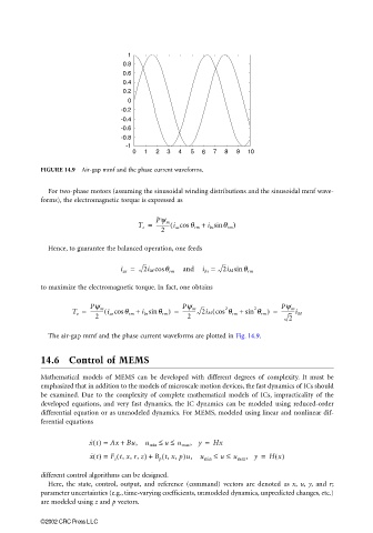
                       FIGURE 14.9  Air-gap mmf and the phase current waveforms.

                         For two-phase motors (assuming the sinusoidal winding distributions and the sinusoidal mmf wave-
                       forms), the electromagnetic torque is expressed as


                                                 T e =  ----------- i as cosθ rm +(  i bs sinθ rm )
                                                      Pψ m
                                                       2
                         Hence, to guarantee the balanced operation, one feeds

                                            i as =  2i M cos  θ rm  and  i bs =  2i M sin  θ rm

                       to maximize the electromagnetic torque. In fact, one obtains


                                                             Pψ m
                                                                                2
                                    Pψ m
                               T e =  ----------- i as cos(  θ rm +  i bs sin θ rm ) =  ----------- 2i M cos θ rm +(  2  sin θ rm ) =  Pψ m
                                                                                        -----------i M
                                     2                        2                           2
                         The air-gap mmf and the phase current waveforms are plotted in Fig. 14.9.
                       14.6 Control of MEMS


                       Mathematical models of MEMS can be developed with different degrees of complexity. It must be
                       emphasized that in addition to the models of microscale motion devices, the fast dynamics of ICs should
                       be examined. Due to the complexity of complete mathematical models of ICs, impracticality of the
                       developed equations, and very fast dynamics, the IC dynamics can be modeled using reduced-order
                       differential equation or as unmodeled dynamics. For MEMS, modeled using linear and nonlinear dif-
                       ferential equations

                                    x ˙ t() =  Ax +  Bu,  u min ≤  u ≤  u max , y =  Hx
                                           (
                                                       (
                                    x ˙ t() =  F z t, x, r, z) +  B p t, x, p)u,  u min ≤  u ≤  u max , y =  H x()
                       different control algorithms can be designed.
                         Here, the state, control, output, and reference (command) vectors are denoted as  x, u, y, and  r;
                       parameter uncertainties (e.g., time-varying coefficients, unmodeled dynamics, unpredicted changes, etc.)
                       are modeled using z and p vectors.

                       ©2002 CRC Press LLC
   303   304   305   306   307   308   309   310   311   312   313