
Page 459 - The Mechatronics Handbook
P. 459
0066_Frame_C19 Page 81 Wednesday, January 9, 2002 5:27 PM
For precise measurements over a wide temperature range, a higher order polynomial should be applied
to determine temperature from resistance. For practical measurements over a narrow range of a few
hundred degrees, the resistance can be treated as linear with temperature. The platinum resistors specified
by ITS 90 are not the same as commercially available in probes. ITS 90 specifies pure, unstrained platinum
wire made into sensors, typically with a resistance of 25.5 Ω at 0°C (Mangum and Furukawa, 1990).
Most RTD elements use commercially pure platinum with a resistance of 100 Ω or 50 Ω at 0°C, although
higher nominal values are sometimes used to minimize the effect of contact and lead resistances in the
circuit and lower resistances are used at high temperatures. There are several differing standard platinum
curves that reflect varying standard purity platinum alloys. While all alloys are nominally pure platinum,
the first-order coefficient for temperatures from 0°C to 100°C of the European standard (DIN 43 760)
is 3.85 mΩ/Ω-K, while the American standard is 3.92 mΩ/Ω-K. Besides these two common coefficients,
there are several other coefficients listed for pure platinum. When purchasing RTDs and RTD reading
equipment, the user should be aware of the standard that applies.
RTD elements can be fabricated as a wire wound onto insulated bobbins or films deposited on
insulating substrates. The size of both the support and the wire, as well as any insulating encapsulation,
will determine the response time of the element. Films are usually smaller than wire wound sensors and
thus have a quicker time response. Due to the need to insulate the RTD from the measured surface,
however, and also to avoid straining the element, even small thin film RTDs have time constants that are
measured in tenths of seconds. In the special case of using a bare wire to measure gas temperatures, the
time constant can be considerably reduced to the tens of microseconds; however, due to the self heating
described below, this is more useful as a form of local anemometry rather than temperature measurement.
The measurement of temperature using a RTD is simply a matter of determining its resistance. The
relation between resistance and temperature is absolute, so no reference temperature is needed, unlike
with thermocouples. However, measuring the resistance of the element is not always simple. There are
three conventional techniques, each of which has its own disadvantages, as will be discussed shortly.
Common to all techniques for measuring remote sensors is the complication of the lead wire resis-
tance. As mentioned above, all metals have a variation in resistance with temperature and thus any lead
wires will act as RTDs. Thus, if the temperature of the wires between the RTD and the reading mechanism
varies, an error will be introduced in the temperature reading unless steps are taken to accommodate
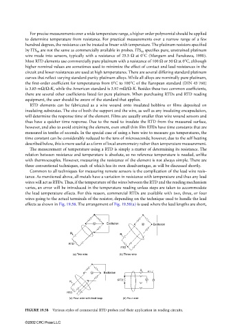
the lead temperature effects. For this reason, commercial RTDs are available with two, three, or four
wires going to the actual terminals of the resistor, depending on the technique used to handle the lead
effects as shown in Fig. 19.58. The arrangement of Fig. 19.58(a) is used where the lead lengths are short,
V Excitation V Excitation
R L R L
RTD
RTD
(a) Two wire (b) Three wire
R L i
V Excitation
RTD V
R L
RTD
(c) Four wire with lead loop (d) Four wire
FIGURE 19.58 Various styles of commercial RTD probes and their application in reading circuits.
©2002 CRC Press LLC