
Page 464 - The Mechatronics Handbook
P. 464
0066_Frame_C19 Page 86 Wednesday, January 9, 2002 5:27 PM
Metal 1 Insulating Layer
Metal 2
AFM Probe
nanometer scale thermocouple
fabricated onto the tip
Sample
heat transfer to thermocouple
from the sample surface Thermocouple Junction
(a) (b)
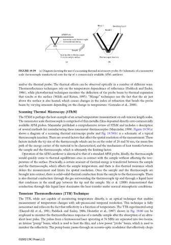
FIGURE 19.59 (a) Diagram showing the use of a scanning thermal microscope probe. (b) Schematic of a nanometer
scale thermocouple maufactured onto the tip of a commercially available AFM cantilever.
and/or the thermal probe. The thermal effects can be observed optically in a number of different ways.
Thermoreflectance techniques rely on the temperature dependence of reflectance (Paddock and Eesley,
1986), while photothermal techniques monitor the deflection of the probe beam by thermal expansion
that results at the surface (Welsh and Ristau, 1995). “Mirage” techniques use the fact that the air just
above the surface is also heated, which causes changes in the index of refraction that bends the probe
beam by varying amounts depending on the change in temperature (Gonzales et al., 2000).
Scanning Thermal Microscopy (SThM)
The SThM is perhaps the best example of an actual temperature measurement on sub-micron length scales.
The nanometer scale thermocouple is comprised of thin metallic films deposited directly onto commercially
available AFM probes. Majumdar published a comprehensive review of SThM and includes a description
of several methods for manufacturing these nanometer thermocouples (Majumdar, 1999). Figure 19.59(a)
shows a diagram of a scanning thermal microscope probe and Fig. 19.59(b) is a schematic of a typical
thermocouple junction. There are several factors that affect the spatial resolution of the measurement. These
factors include the tip size of the thermocouple which can be on the order of 20 and 50 nm, the mean free
path of the energy carrier of the material to be characterized, and the mechanism of heat transfer between
the sample and the thermocouple, which is ultimately the limiting factor.
Operation of the AFM cantilever is identical to that of a standard AFM probe. Ideally, the thermocouple
would quickly come to thermal equilibrium once in contact with the sample without affecting the tem-
perature of the surface. Practically, a certain amount of thermal energy is transferred between the sample
and the thermocouple, which affects the sample temperature, and there is also thermal resistance which
delays the measurement and limits the spatial resolution. Once the sample and the thermocouple are
brought into contact, there is solid–solid thermal conduction from the sample to the thermocouple. There
is also thermal conduction through the gas surrounding the thermocouple tip and through a liquid layer
that condenses in the small gap between the tip and the sample. Shi et al. (2000) demonstrated that
conduction through this liquid layer dominates the heat transfer under normal atmospheric conditions.
Transient Thermoreflectance (TTR) Technique
The TTR, while not capable of monitoring temperature directly, is an optical technique that enables
measurement of temperature changes with sub-picosecond temporal resolution. This technique is fully
noncontact and relies on the fact that reflectivity is a function of temperature. The TTR experimental setup
(Elsayed-Ali et al., 1991; Paddock and Eesley, 1986; Hostetler et al., 1997) shown in Fig. 19.60 can be
employed to monitor the thermoreflectance response of a metallic sample after the absorption of an ultra-
short laser pulse. The pulses from a femtosecond laser operating at 76 MHz are separated into two beams,
an intense “pump” beam, which is used to heat the film, and a low power “probe” beam, which is used to
monitor the reflectivity. The pump beam passes through an acousto-optic modulator that effectively chops
©2002 CRC Press LLC