
Page 468 - The Mechatronics Handbook
P. 468
0066_frame_C19 Page 90 Wednesday, January 9, 2002 5:32 PM
8
Emitted Signal
7
6 5
Amplitude 4 3 Time-of-Flight Return Signal
2
1
0
0 5 10 15 20
Time
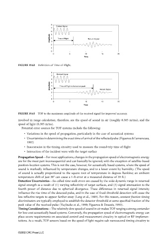
FIGURE 19.62 Definition of Time-of-Flight.
8
Emitted Signal
7
6 5
Amplitude 4 3 Time-of-Flight to locked-on peak
2 Return Signal
1
0
0 5 10 15 20
Time
FIGURE 19.63 TOF to the maximum amplitude of the received signal for improved accuracy.
involved in range calculation, therefore, are the speed of sound in air (roughly 0.305 m/ms), and the
speed of light (0.305 m/ns).
Potential error sources for TOF systems include the following:
• Variations in the speed of propagation, particularly in the case of acoustical systems
• Uncertainties in determining the exact time of arrival of the reflected pulse (Figueroa & Lamancusa,
1992)
• Inaccuracies in the timing circuitry used to measure the round-trip time of flight
• Interaction of the incident wave with the target surface
Propagation Speed—For most applications, changes in the propagation speed of electromagnetic energy
are for the most part inconsequential and can basically be ignored, with the exception of satellite-based
position-location systems. This is not the case, however, for acoustically based systems, where the speed of
sound is markedly influenced by temperature changes, and to a lesser extent by humidity. (The speed
of sound is actually proportional to the square root of temperature in degrees Rankine; an ambient
temperature shift of just 30° can cause a 1-ft error at a measured distance of 35 ft.)
Detection Uncertainties—So-called time-walk errors are caused by the wide dynamic range in returned
signal strength as a result of (1) varying reflectivity of target surfaces, and (2) signal attenuation to the
fourth power of distance due to spherical divergence. These differences in returned signal intensity
influence the rise time of the detected pulse, and in the case of fixed-threshold detection will cause the
less reflective targets to appear further away (Lang et al., 1989). For this reason, constant fraction timing
discriminators are typically employed to establish the detector threshold at some specified fraction of the
peak value of the received pulse (Vuylsteke et al., 1990; Figueroa & Doussis, 1993).
Timing Considerations—The relatively slow speed of sound in air makes TOF ranging a strong contender
for low-cost acoustically based systems. Conversely, the propagation speed of electromagnetic energy can
place severe requirements on associated control and measurement circuitry in optical or RF implemen-
tations. As a result, TOF sensors based on the speed of light require sub-nanosecond timing circuitry to
©2002 CRC Press LLC