
Page 472 - The Mechatronics Handbook
P. 472
0066_frame_C19 Page 94 Wednesday, January 9, 2002 5:32 PM
Transmitter
Modulator
Receiver
Output
Preamp Filter Phase Locked
Loop
FIGURE 19.68 The microwave sensor, unlike the motion detector, requires a separate transmitter and receiver
(adapted from Williams, 1989).
8
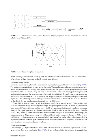
Emitted Signal
7
6 5
Amplitude 4 3 Phase Return Signal
2
1
0
0 1 2 3 4 5
Time
FIGURE 19.69 Range from phase measurement.
Worst-case range measurement accuracy is ±5 cm, with typical values of around ±2 cm. The pulsed near-
infrared laser is Class-1 eye-safe under all operating conditions.
Microwave Range Sensors
Microwave technology may be used to measure motion, velocity, range, and direction of motion (Fig. 19.68).
The sensors are rugged since they have no moving parts. They can be operated safely in explosive environ-
ments, because the level of energy used is very low (no risk for sparks). Their operating temperatures
range from −55°C to +125°C. They can work in environments with dust, smoke, poisonous gases, and
radioactivity (assuming the components are hardened for radiation). Typically microwave sensors are
used to measure ranges from 25 to 45,000 mm, but longer ranges are possible depending on power and
object size. The reflected power returning to the receiver decreases as the fourth power of the distance
to the object. Typical wavelength used ranges from 1 to 1000 mm.
Time-of-flight is in the order 2 ns per foot of range (reach the target and return). This translates into
10.56 ms per mile of range. Measuring short ranges may pose a problem. For 1 in. resolution, the circuit
must resolve 167 ps. An alternate method more suitable to measure short distances is based on a frequency
sweep of the signal generator. In this case, the return signal remains at the initial frequency (usually
10.525 GHz), and it is compared with the current frequency changed by a sweep rate. For example, to
measure a range of 3 ft, one may sweep at 5 MHz/ms. After 6 ns, the frequency changes by 30 Hz (6 ns ×
5 MHz/0.001 s). In this case, 0.0256 mm (0.001 in.) may be resolved easily. When using this method, a
signal amplifier that increases gain with frequency is necessary. See section “Frequency Modulation” for
more details on frequency modulation methods.
Phase Measurement
Time-of-flight (TOF) is defined as a phase shift between emitted and received signals when the dis-
tance is less than one wavelength (Fig. 19.69). Given a phase shift f, the distance is calculated as
©2002 CRC Press LLC