Page 476 - The Mechatronics Handbook
P. 476

0066_frame_C19  Page 98  Wednesday, January 9, 2002  5:32 PM


                                                10
                                                9  Frequency f = f 0  + kt  Frequency f = f 0  + k (t -t f )
                                                8                      Emitted Signal
                                                7
                                                6
                                             Amplitude  5  Time-of-flight
                                                4
                                                     t f               Return Signal
                                                3
                                                2
                                                1
                                                0
                                              -2       3     t  8      13      18
                                                              Time

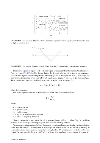
                       FIGURE 19.73  The frequency difference between the emitted signal and received signal is proportional to the time-
                       of-flight at any given time.

                                            f
                                                      2d/c


                                            f o
                                                                             t


                       FIGURE 19.74  The received frequency curve is shifted along the time axis relative to the reference frequency.
                         The received signal is compared with a reference signal taken directly from the transmitter. The received
                       frequency curve (Fig. 19.74) will be displaced along the time axis relative to the reference frequency curve
                       by an amount equal to the time required for wave propagation to the target and back. (There might also
                       be a vertical displacement of the received waveform along the frequency axis, due to the Doppler effect.)
                       These two frequencies when combined in the mixer produce a beat frequency F b :

                                                             (
                                                    F b =  ft() fT + t) =  kT
                                                           –
                       where k is a constant.
                         This beat frequency is measured and used to calculate the distance to the object:

                                                               F b c
                                                          d =  -------------
                                                              4F r F d
                       where
                         d  = range to target,
                         c  = speed of light,
                         F b  = beat frequency,
                         F r   = repetition (modulation) frequency,
                         F d  = total FM frequency deviation.

                         Distance measurement is therefore directly proportional to the difference or beat frequency and is as
                       accurate as the linearity of the frequency variation over the counting interval.
                         Advances in wavelength control of laser diodes now permit this ultrasonic and radar ranging technique
                       to be used with lasers. The frequency or wavelength of a laser diode can be shifted by varying its
                       temperature. Consider an example where the wavelength of an 850-nm laser diode is shifted by 0.05 nm
                       in 4 µs: the corresponding frequency shift is 5.17 MHz/ns. This laser beam, when reflected from a surface


                       ©2002 CRC Press LLC
   471   472   473   474   475   476   477   478   479   480   481