
Page 477 - The Mechatronics Handbook
P. 477
0066_frame_C19 Page 99 Wednesday, January 9, 2002 5:32 PM
P
1
B
P
3
A
P
2
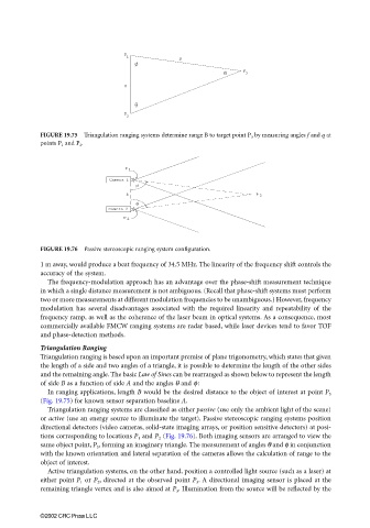
FIGURE 19.75 Triangulation ranging systems determine range B to target point P 3 by measuring angles f and q at
points P 1 and P 2 .
P 1
Camera 1
A P 3
Camera 2
P 2
FIGURE 19.76 Passive stereoscopic ranging system configuration.
1 m away, would produce a beat frequency of 34.5 MHz. The linearity of the frequency shift controls the
accuracy of the system.
The frequency-modulation approach has an advantage over the phase-shift measurement technique
in which a single distance measurement is not ambiguous. (Recall that phase-shift systems must perform
two or more measurements at different modulation frequencies to be unambiguous.) However, frequency
modulation has several disadvantages associated with the required linearity and repeatability of the
frequency ramp, as well as the coherence of the laser beam in optical systems. As a consequence, most
commercially available FMCW ranging systems are radar based, while laser devices tend to favor TOF
and phase-detection methods.
Triangulation Ranging
Triangulation ranging is based upon an important premise of plane trigonometry, which states that given
the length of a side and two angles of a triangle, it is possible to determine the length of the other sides
and the remaining angle. The basic Law of Sines can be rearranged as shown below to represent the length
of side B as a function of side A and the angles θ and φ:
In ranging applications, length B would be the desired distance to the object of interest at point P 3
(Fig. 19.75) for known sensor separation baseline A.
Triangulation ranging systems are classified as either passive (use only the ambient light of the scene)
or active (use an energy source to illuminate the target). Passive stereoscopic ranging systems position
directional detectors (video cameras, solid-state imaging arrays, or position sensitive detectors) at posi-
tions corresponding to locations P 1 and P 2 (Fig. 19.76). Both imaging sensors are arranged to view the
same object point, P 3 , forming an imaginary triangle. The measurement of angles θ and φ in conjunction
with the known orientation and lateral separation of the cameras allows the calculation of range to the
object of interest.
Active triangulation systems, on the other hand, position a controlled light source (such as a laser) at
either point P 1 or P 2 , directed at the observed point P 3 . A directional imaging sensor is placed at the
remaining triangle vertex and is also aimed at P 3 . Illumination from the source will be reflected by the
©2002 CRC Press LLC