
Page 474 - The Mechatronics Handbook
P. 474
0066_frame_C19 Page 96 Wednesday, January 9, 2002 5:32 PM
MDARS Maximum Range
Security
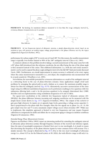
FIGURE 19.70 By limiting the maximum distance measured to be less than the range ambiguity interval R a ,
erroneous distance measurements can be avoided.
Reference
R
V
Signal
C 1
XOR Gate
Phase Difference
FIGURE 19.71 At low frequencies typical of ultrasonic systems, a simple phase-detection circuit based on an
exclusive-or gate will generate an analog output voltage proportional to the phase difference seen by the inputs
(adapted from Figueroa & Barbieri, 1991a).
performance for a phase angle of 90° to worst case at 0 and 180°. For this reason, the useable measurement
range is typically even further limited to 90% of the 180° ambiguity interval (Chen et al., 1993).
A common solution to this problem involves taking a second measurement of the same scene but with
a 90° phase shift introduced into the reference waveform, the net effect being the sine of the phase angle
is then measured instead of the cosine. This additional information (i.e., both sine and cosine measure-
ments) can be used to expand the phase angle ambiguity interval to the full 360° limit previously discussed
(Scott, 1990). Furthermore, an overall improvement in system accuracy is achieved, as for every region
where the cosine measurement is insensitive (i.e., zero slope), the complementary sine measurement will
be at peak sensitivity (Woodbury et al., 1993).
Nevertheless, the unavoidable potential for erroneous information as a result of the ambiguity interval
is a detracting factor in the case of phase-detection schemes. Some applications simply avoid such
problems by arranging the optical path in such a fashion as to ensure the maximum possible range is
always less than the ambiguity interval (Fig. 19.70). Alternatively, successive measurements of the same
target using two different modulation frequencies can be performed, resulting in two equations with two
unknowns, allowing both x and n (in the previous equation) to be uniquely determined. Kerr (1988)
describes such an implementation using modulation frequencies of 6 and 32 MHz.
For square-wave modulation at the relatively low frequencies typical of ultrasonic systems (20–
200 kHz), the phase difference between incoming and outgoing waveforms can be measured with the
simple linear circuit shown in Fig. 19.71 (Figueroa & Barbieri, 1991a). The output of the exclusive-or
gate goes high whenever its inputs are at opposite logic levels, generating a voltage across capacitor C 1
that is proportional to the phase shift. For example, when the two signals are in phase (i.e., φ = 0), the
gate output stays low and V is zero; maximum output voltage occurs when φ reaches 180°. While easy
to implement, this simplistic approach is limited to very low frequencies and may require frequent
calibration to compensate for drifts and offsets due to component aging or changes in ambient conditions
(Figueroa & Lamancusa, 1992).
Extended Range Phase Measurement Systems
Figueroa and Barbieri (1991a; 1991b) report an interesting method for extending the ambiguity interval
in ultrasonic phase-detection systems through frequency division of the received and reference signals.
Since the span of meaningful comparison is limited (best case) to one wavelength, λ, it stands to reason
that decreasing the frequency of the phase detector inputs by some common factor will increase λ by a
similar amount. The concept is illustrated in Fig. 19.72. Due to the very short wavelength of ultrasonic
energy (i.e., about 0.25 in. for the Polaroid system at 49.1 kHz), the total effective range is still only 4 in.
©2002 CRC Press LLC